Sensor Size and Lens Compatibility in Machine Vision: Image Circle, Vignetting, and Relative Illumination
How to match a lens to a sensor: coverage math, vignetting mechanisms, and the relative illumination curve that combines them.
A lens matches a sensor when its image circle diameter equals or exceeds the sensor diagonal, with margin left over for corner sharpness. That comparison is necessary but not sufficient: after coverage, an engineer still has to check mechanical vignetting, aperture-dependent optical vignetting, the fixed cos4 falloff of the projection, and chief ray angle (CRA) match to the sensor's microlens array. This page covers all four checks. For sensor format dimensions, naming conventions, and diagonal charts by format, see the CMOS sensor size guide.
How do I know if a lens covers my sensor?
Compare the lens image circle diameter to the sensor diagonal. If the image circle equals or exceeds the diagonal, coverage is sufficient; if it is smaller, the sensor corners fall outside the illuminated area and record black. Sensor diagonal is calculated from the active area, not from the format name.
Compatibility has two independent parts, mechanical and optical, and both have to hold. A lens is mechanically compatible when it mounts correctly and reaches focus at the intended working distance. A lens is optically compatible when its image circle covers the sensor and its chief ray angle and relative illumination fall within the sensor's tolerances. An engineer can confirm mount type, thread pitch, and flange distance and still end up with vignetting if the image circle is too small. The two checks do not imply each other.
For a 1/2-inch sensor with a 6.4 × 4.8mm active area: diagonal = √(40.96 + 23.04) = √64 = 8.0mm. Any lens paired with that sensor needs an image circle of at least 8.0mm, and a margin above that for corner quality.
Sensor format reference and minimum image circle
| Sensor format | Typical active area (mm) | Diagonal (mm) | Minimum image circle | Typical lens class |
|---|---|---|---|---|
| 1/4" | 3.2 × 2.4 | 4.0 | 4.0mm+ | M12 |
| 1/3" | 4.8 × 3.6 | 6.0 | 6.0mm+ | M12 |
| 1/2.7" | 5.3 × 4.0 | 6.6 | 6.6mm+ | M12 |
| 1/2.9" | 5.6 × 3.2 | 6.4 | 6.4mm+ | M12 |
| 1/2.5" | 5.8 × 4.3 | 7.2 | 7.2mm+ | M12 |
| 1/2" | 6.4 × 4.8 | 8.0 | 8.0mm+ | M12 or C-mount |
| 1/1.8" | 7.2 × 5.4 | 9.0 | 9.0mm+ | M12 or C-mount |
| 1/1.7" | 7.6 × 5.7 | 9.5 | 9.5mm+ | M12 or C-mount |
| 2/3" | 8.8 × 6.6 | 11.0 | 11.0mm+ | C-mount |
| 1" | 12.8 × 9.6 | 16.0 | 16.0mm+ | C-mount |
| 1.1" | 13.3 × 11.3 | 17.5 | 17.5mm+ | C-mount |
Active area dimensions vary by manufacturer and sensor model, even within the same format label. Use the exact width and height from the sensor datasheet for the diagonal calculation. For a full format-naming reference and dimension charts, see the CMOS sensor size guide and the image sensors database.
Lens datasheets specify image circle as an explicit millimeter value or a rated sensor format. Prefer the millimeter value: format names are not standardized, and a 1/1.8-inch label from one manufacturer can differ from another by several tenths of a millimeter. Image circle is specified at infinity focus unless noted; at close working distances it typically increases slightly as the barrel extends.
What is the image circle of a lens?
Image circle is the diameter of the circular illuminated area a lens projects onto the image plane at infinity focus, measured in millimeters. A lens does not illuminate the focal plane uniformly. It forms a cone of converging rays that intersects the image plane as a circle. Inside the circle the lens forms a usable image; beyond it, illumination rolls off rapidly toward zero, so pixels well outside the circle record black.
The sensor is rectangular and sits at the image plane, capturing whatever portion of the circle falls over its active area. The farthest point from sensor center is a corner, at half the sensor diagonal. For every pixel to receive light, the image circle has to reach all four corners, which is why sensor diagonal, not sensor width or height alone, is the number that matters.
Image circle and sensor size are properties of two different components and are frequently confused. Image circle is a lens specification: the diameter of the light cone the lens produces. Sensor size is a sensor specification: the physical dimensions of the active pixel area. A lens and sensor pair is compatible when the two numbers are compared directly (image circle diameter against sensor diagonal), not when either spec looks large in isolation.
A lens can cover the sensor and still perform poorly in the corners for three separate reasons: MTF (resolution) drops toward the edge of the rated image circle, CRA mismatch reduces corner sensitivity even with full coverage, and distortion increases toward the corners and may exceed tolerance for metrology work. Image circle coverage is the first filter, not the last check; see CRA hand-off below.
A margin of 10-15% above the sensor diagonal is common practice for applications where corner quality matters, because a lens rated for exactly the sensor's diagonal places those corners at the worst-performing field position the lens has.
Lens datasheets specify image circle in one of two ways: an explicit millimeter value, or a rated sensor format such as "1/1.8-inch." The two are related but not identical, because format names describe a historical vidicon-tube convention and were never standardized to a fixed millimeter diagonal. Two lenses both marketed as "1/1.8-inch" can have image circles that differ by several tenths of a millimeter depending on the manufacturer's internal convention. When a datasheet gives both, use the millimeter value for the compatibility calculation and treat the format label as a rough cross-check only.
Image circle is normally specified at infinity focus. At close working distances the lens barrel extends and the projected circle typically grows slightly, so a lens that is marginal at infinity often has more coverage margin at a short working distance. For macro or close-focus applications where the working distance is fixed and short, confirm the image circle at that actual distance rather than assuming the infinity-focus datasheet number applies unchanged.
Why can a lens fit mechanically but still vignette?
Lens mount compatibility is a mechanical specification: thread pitch, flange distance, and physical clearance. It says nothing about the image circle the lens projects. Mount type, flange distance, and image circle are three independent parameters, and all three have to pass for the system to work.
A 1/3-inch M12 lens threads onto a 1/2-inch sensor camera using the same M12 holder without resistance: the threads engage, the lens locks down, and the assembly looks correct. But the 1/3-inch lens has an image circle around 6mm, and the 1/2-inch sensor has an 8mm diagonal. The corners of that sensor receive no light, and the image shows hard dark borders. This is a common sensor-lens compatibility mistake, because it is invisible until a prototype is built and a flat-field test is run.
For C-mount and CS-mount systems, flange distance is the additional complication: a CS lens can thread onto a C-mount body and fail to reach infinity focus because the flange distance is off by 5mm, a separate problem from image circle but equally easy to miss. For a full treatment of mount families and flange distance, see the lens mount guide: M12 vs C-mount vs CS-mount.
The practical checklist for engineers evaluating a candidate lens is four items, not one: mount type matches the camera body, flange distance matches (or is corrected with a spacer), image circle covers the sensor diagonal with margin, and CRA is within tolerance for the sensor's microlens array. Confirming only the mount and calling the lens "compatible" skips the two checks most likely to produce a visible defect in the field.
What causes vignetting in machine vision?
Vignetting has three distinct mechanisms, and each requires a different fix. Mechanical vignetting is physical clipping: the lens image circle does not cover the full sensor diagonal, so corner pixels receive no light regardless of aperture or illumination. Optical vignetting is aperture-dependent illumination roll-off, caused by off-axis ray bundles seeing a smaller effective aperture than on-axis bundles. It is worst wide-open and improves when you stop down. Natural falloff follows the cos4 law for rectilinear projection with negligible pupil aberration; stopping down does not change it, since it is a function of projection geometry rather than aperture.
Confusing these three costs engineering time, because the fix for one does nothing for the others. A lens rated for a larger sensor than you need eliminates mechanical vignetting, but it does not touch optical vignetting or cos4 falloff, both of which continue to operate at the corners.
Mechanical vignetting
This is the image-circle case covered above: the illuminated cone is smaller than the sensor diagonal, and corner pixels record black or near-black. It is the most common cause of severe corner darkening in compact M8 and M12 systems where lens and sensor formats are mismatched. A 1/2.7" sensor has a diagonal of about 6.6mm; a lens rated for that format guarantees coverage only up to that diagonal. Used on a larger sensor, mechanical vignetting appears regardless of aperture or illumination settings.
Optical vignetting (aperture-dependent)
Optical vignetting is mechanical clipping of oblique ray bundles by the rims of lens elements and the barrel itself: off-axis bundles pass through a series of apertures that are not all centered on the same axis from that ray's point of view, so part of the bundle is physically cut off before it reaches the stop, and the effective aperture seen off-axis narrows into a lens-shaped "cat's-eye" pupil. Because it is a physical clipping effect tied to the size of the aperture relative to the element rims, it is worst at wide apertures and improves as you stop down: a smaller aperture reduces how much of the oblique bundle the barrel and element edges intercept. For C-mount lenses with an adjustable iris ring, stopping down from F/2.8 to F/5.6 typically reduces optical vignetting by a significant fraction. Machine vision systems can absorb this tradeoff because illumination is usually controlled programmatically with LED ring lights, backlight arrays, or structured lighting. M12 lenses typically have no adjustable iris, so optical vignetting is generally fixed at the time of manufacture; a minority of M12-mount lenses offer manual iris variants that allow some field adjustment.
Natural (cos4) falloff
At a 20° half-angle, cos4(20°) ≈ 0.78, a 22% illuminance drop. At 30° it is about 44%. At 45° it is about 75%. This raw formula holds for rectilinear projection with negligible pupil aberration and unit pupil magnification; it is present even in an aberration-free rectilinear lens and does not respond to stopping down, so stopping down while correcting for optical vignetting often reveals the underlying cos4 component more clearly. Wide-angle and fisheye designs deliberately depart from this ideal, using barrel distortion and pupil aberration to beat the raw cos4 number at large field angles, so the formula should be treated as a worst-case estimate for those lenses rather than an exact prediction. Note also that the relevant half-angle for corner falloff is the diagonal (corner) half-angle, not the horizontal half-angle: a short-focal-length M12 lens with a 60° horizontal full field has roughly a 31° horizontal half-angle, but its corner half-angle (set by the sensor diagonal) is larger, and it is the corner half-angle that determines worst-case natural illuminance loss.
| Symptom | Likely mechanism | First check | Fixable by stopping down? |
|---|---|---|---|
| Hard black corners, sharp boundary | Mechanical vignetting | Compare image circle to sensor diagonal | No; a different lens is required |
| Smooth radial falloff, improves stopped down | Optical vignetting | Measure relative illumination at multiple F-numbers | Yes, on C-mount with an iris ring |
| Smooth radial falloff, unchanged stopped down | Natural (cos4) falloff | Calculate expected falloff from the corner (diagonal) field half-angle | No; it is governed by projection geometry, not aperture. Magnitude depends on lens design (rectilinear vs. wide-angle/fisheye) |
| Corner darkening with color shift | CRA mismatch (see below) | Compare lens CRA curve to sensor microlens spec | No; brightness correction does not fix color error |
A flat-field correction can normalize the appearance of any of these in software, but it amplifies corner noise in proportion to the correction factor and does not restore contrast or color accuracy that CRA mismatch removes. For applications where corner image quality drives the pass/fail decision (precision inspection, edge features near the field boundary), select an optical stack that minimizes vignetting at the source and treat flat-field correction as cleanup for residual non-uniformity, not the primary fix.
What is relative illumination in a lens?
Relative illumination is the normalized brightness at a field position, expressed as a ratio to the illuminance at the optical axis. A lens with 70% relative illumination at the corner delivers 30% less light there than at the center under identical exposure. It is the umbrella measurement that combines mechanical vignetting, optical vignetting, natural falloff, and CRA mismatch into a single curve or field map. It is not a synonym for any one of them.
A low distortion spec does not imply high corner relative illumination. Distortion describes where image points land geometrically (the mapping r(θ) from field angle to image height), and that same mapping directly sets how illuminance is spread across the image plane, so relative illumination is not actually independent of distortion. The defensible statement is narrower: a lens with under 0.2% distortion can still show 50% relative illumination at the corner, so good geometric accuracy says nothing about corner brightness, and both specs need to be checked separately for dimensional-inspection work.
| Contributing mechanism | What it changes | What fixes it |
|---|---|---|
| cos4 roll-off | Illuminance falls with the fourth power of field half-angle under rectilinear projection; wide-angle and fisheye designs can beat this raw figure with deliberate distortion and pupil aberration | Largely fixed by projection geometry for rectilinear designs; accept it or choose a longer focal length, or a lens whose projection is intentionally engineered to reduce it |
| Optical (aperture) vignetting | Oblique ray bundles see a reduced effective aperture | Stop down the iris on C-mount; most M12 lenses are fixed at design |
| Mechanical (image-circle) vignetting | Illuminated cone smaller than sensor diagonal | Use a lens with a larger rated image circle |
| CRA mismatch | Principal ray angle at the corner mismatches sensor microlens design | Select a lens with a CRA profile matched to the sensor spec |
| Filter/window stack | Coating passband shifts and higher Fresnel loss at the oblique angles corner rays actually see, plus added aberration in converging light | Use AR-coated optics rated for the lens's CRA range; budget filter stack into the CRA analysis |
Wide-angle lenses make the angle-dependent mechanisms worse at once: cos4 falloff, optical vignetting, CRA mismatch, and filter-stack losses all grow as larger field angles push half-angle, oblique ray geometry, and CRA toward their limits simultaneously. A 100° diagonal FOV lens has corner half-angles around 50°, where raw cos4 falloff is roughly 83%, so corners would receive about 17% of center illuminance from that mechanism alone before vignetting or CRA effects are added, though this raw cos4 figure assumes rectilinear projection and unit pupil magnification; real wide-angle and fisheye designs deliberately introduce distortion and pupil aberration to beat this number substantially, so it overstates actual corner falloff for those lenses. Using a lens rated for a sensor larger than the one in use is one practical, no-cost way to reduce optical vignetting and put the active corners in a better-corrected zone of the image circle. It does not, however, reduce cos4 falloff itself, since that depends on the field angle subtended by the sensor, which is set by focal length and sensor size rather than by the lens's rated image circle.
Relative illumination is measured on an optical bench with a uniform, extended Lambertian source (typically an integrating sphere) filling the lens's field of view, while a detector scans the image field to record brightness at each position; a fixed collimated source only illuminates a single field point and cannot produce the full curve on its own. An equivalent method rotates a collimator through field angles with appropriate radiometric bookkeeping at each angle. Some manufacturers publish only a single worst-case corner number; others give the full field map or values at 70% and 100% field height. If a datasheet only states the 70% field-height number, ask for or measure the full-corner value directly, since the worst falloff is always at 100% field height and a mid-field number can understate it substantially.
Filters and cover glass in the optical path add another variable. A flat filter or window does not increase the incidence angle of oblique corner rays; inside the glass those rays actually refract to a smaller angle than the lens's chief ray angle in air. The measurable degradation instead comes from the angle-dependent blue-shift of interference-filter passbands (an IR-cut or bandpass coating designed for near-normal incidence transmits differently at the steep angles seen at the corners), increased Fresnel and coating reflectance losses at oblique incidence, and additional spherical or astigmatic aberration the plate introduces into already-converging corner ray bundles. Account for filter stack thickness, coating angle sensitivity, and CRA in the same relative illumination budget used for the lens alone, particularly for wide-angle designs where corner rays are already at a steep angle before any added glass.
Does CRA matter once the image circle is large enough?
Yes. Chief ray angle (CRA) is the angle at which the principal ray exits the lens at a given field position. Near the sensor center it is close to zero; at the corners it is larger, and light exits obliquely. CMOS sensors have microlens arrays over each pixel shaped for a specific CRA profile that varies with field position. If the lens CRA at the corner does not match the sensor's microlens design angle, the microlenses deflect light away from the photodiode rather than onto it, and corner sensitivity drops.
The result is corner luminance drop or color shading, symptoms that look like vignetting but persist even when the image circle is fully adequate. Brightness correction in software does not fix the underlying angular mismatch, and it does not restore the color accuracy or resolution lost at the corners. CRA mismatch is most pronounced with wide-angle M12 lenses used on high-resolution sensors, where both the field angle and the pixel pitch push microlens tolerances to their limit.
Request the lens CRA profile at 0°, half-field, and full-field positions, and compare it against the sensor's specified microlens CRA at the same field heights. A CRA mismatch at full field that exceeds the sensor's rated CRA acceptance tolerance produces measurable corner shading. That tolerance is sensor-specific, so compare the lens CRA against the sensor datasheet's stated value rather than assuming a fixed threshold. This data is not always included in a headline datasheet. Ask the manufacturer directly if it is missing.
CRA hand-off is the last of the four checks in the selection workflow below: coverage, then mechanical/optical/natural vignetting, then relative illumination, then CRA. All four need to pass before prototype lock, not just the first one that happens to be easy to measure.
CRA mismatch is also asymmetric in ways vignetting is not. If the lens-to-sensor alignment has any tilt or decenter, the CRA error at one edge of the frame can differ from the opposite edge, producing a brightness or color gradient that is not radially symmetric around the optical axis. A symmetric radial falloff on a flat-field test points to vignetting or natural falloff; an asymmetric gradient points to alignment error, CRA mismatch compounded by tilt, or contamination on the lens or cover glass. Distinguishing these before changing the optical stack saves a redesign cycle when the actual fault is an assembly tolerance.
On color sensors, CRA mismatch shows up as more than a luminance drop: red, green, and blue pixels have slightly different angular sensitivities, so a mismatched CRA profile produces a color shift toward the corners in addition to brightness loss. This color artifact is not removable with a luminance-only flat-field correction, which is one of the clearest diagnostic signs that the underlying cause is CRA rather than plain vignetting.
Fisheye fill factor: the intentional exception to the coverage rule
Standard lenses are specified so the image circle equals or exceeds the sensor diagonal. Fisheye systems are the main case where that relationship is deliberately varied, because a fisheye lens has a defined image circle just like any other lens. What changes with sensor choice is how much of that projection the sensor actually captures.
| Fill mode | Image circle vs sensor | What the sensor sees | Typical use |
|---|---|---|---|
| Circular fisheye | Image circle smaller than the sensor's short dimension | Complete circular image with black corners; maximum fisheye FOV visible | 360-degree imaging, panoramic capture |
| Full-frame fisheye | Image circle at or just above sensor diagonal | Fisheye content fills the frame edge to edge | SLAM, robotics, surround-view systems |
| Cropped fisheye | Image circle larger than sensor diagonal | Sensor captures only the central region; narrower effective FOV, less apparent distortion | Compact embedded builds using a wide fisheye at moderate FOV |
A complete circular image requires the image circle diameter to fit inside the sensor's short dimension, not just its diagonal: a circle can be smaller than the diagonal and still get clipped top and bottom if it exceeds the sensor height. For example, a 195° fisheye designed around a 4.7mm image circle produces circular fisheye output only on a sensor whose short side exceeds 4.7mm; on a 1/3-inch sensor (4.8 × 3.6mm, 6.0mm diagonal) the 3.6mm height is smaller than the 4.7mm circle, so the circle is clipped top and bottom despite the larger diagonal, so the result is not a complete circular image. Full-frame fisheye occurs when the image circle is at or just above the sensor diagonal, filling the frame edge to edge. This is unlike every other lens category on this page, where the goal is always image circle above sensor diagonal with margin; for fisheye systems the ratio is a deliberate design choice. For projection and distortion tradeoffs specific to wide fields of view, see wide-angle lenses and fisheye camera lens distortion.
The practical consequence for machine vision engineers is that the same fisheye lens gives different effective field coverage and different apparent distortion depending on which sensor it is paired with. A compact embedded design that needs a moderate field of view in a small package can deliberately pair a wide fisheye with a smaller sensor to get cropped fisheye output: narrower coverage, but less visible barrel distortion and a smaller optical stack than a purpose-built moderate-FOV lens would require. Engineers evaluating a fisheye datasheet should check which fill mode the published FOV and distortion numbers assume, since a full-frame-fisheye spec does not describe performance in cropped mode.
Commonlands product examples across formats
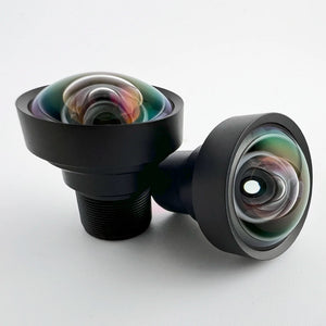
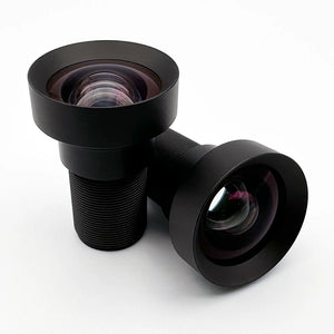
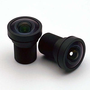
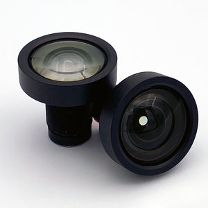
These three products show how image circle, sensor format, and mount scale together, and where vignetting and relative illumination considerations differ between them.
Browse the full M12 lens collection and C-mount lens collection.
Lens picks by sensor format
For a rectilinear lens the coverage test is one comparison: the image circle has to reach the sensor diagonal. This table maps common machine vision formats from 1/4-inch to 1-inch to a Commonlands lens whose published image circle clears that diagonal. The diagonal column reuses the values from the sensor format reference above, so the two tables agree.
| Sensor format | Diagonal (mm) | Example sensors / use | Recommended Commonlands lens | Lens image circle |
|---|---|---|---|---|
| 1/4" | 4.0 | Low-cost surveillance, webcams | CIL343 4.4mm M12 | Covers 1/1.8" (~9.0mm); oversized, wide margin |
| 1/3" | 6.0 | Security cameras, drones | CIL062 6mm M12 | 9.0mm |
| 1/2" | 8.0 | Compact cameras, drones | CIL085 8mm M12 | 8.9mm |
| 1/1.8" | 9.0 | Surveillance and robotics; IMX678 | CIL368 7mm M12 | 9.2mm |
| 2/3" | 11.0 | Global-shutter machine vision | CIL522 12mm C-mount | 11.4mm |
| 1" | 16.0 | Global-shutter machine vision | CIL544 25mm C-mount | 17.6mm |
Each row names the Commonlands lens whose datasheet image circle equals or exceeds the format diagonal, with the diagonal read from the reference table above rather than recalculated. At 1/2-inch and below, the compact M12 optics project more circle than the format needs, and that surplus is useful: it seats the active corners inside a better-corrected zone of the image circle. Confirm the field of view at your working distance with the field of view calculator before ordering samples.
The CIL544 covers 1.1-inch sensors, the top of the Commonlands C-mount range. For larger formats such as 4/3-inch or APS-C, C-mount and large-format lenses from Fujinon, Kowa, or Edmund Optics are the standard options.
A quick selection workflow for matching a lens to a sensor
Run these steps before committing to a lens at prototype lock. Each step eliminates candidates; later steps refine among the ones that passed.
- Calculate sensor diagonal. Use the active area width and height from the sensor datasheet: diagonal = √(width² + height²). Format names alone can differ by 0.5mm or more between manufacturers using the same label.
- Filter by image circle. Keep only lenses with image circle ≥ sensor diagonal. For corner-critical applications, filter to image circle ≥ sensor diagonal × 1.1.
- Confirm mount and flange distance. Verify the mount type matches the camera and the flange focal distance is correct; a lens with the right image circle on the wrong mount still fails to focus.
- Classify the vignetting risk. Estimate the field half-angle at your sensor corner and calculate expected cos4 falloff. Note whether the lens has an adjustable iris to manage optical vignetting.
- Check CRA against the sensor microlens spec. Compare the lens CRA profile (typically given at 0°, half-field, and full-field) to the sensor's microlens CRA design. A CRA mismatch at full field that exceeds the sensor's rated CRA acceptance tolerance produces measurable corner shading. That tolerance is sensor-specific, so compare the lens CRA against the sensor datasheet's stated value rather than assuming a fixed threshold.
- Review corner MTF and distortion at your sensor size. Center MTF does not predict corner performance, and distortion at the rated format edge may differ from distortion at your actual sensor crop.
- Verify working distance range. All of the above parameters are specified at or near the lens's design working distance; confirm they still hold at the distance your application actually uses.
- Run a flat-field test at the bench. Capture a uniformly lit flat field before prototype lock and inspect corner uniformity. This catches CRA mismatch, vignetting, and edge shading that are not always visible in complex scenes.
Use the field of view calculator and EFL calculator to confirm field coverage before ordering samples.
Look up active area dimensions directly in the image sensors database.
Run these checks in order rather than in parallel, because each step is cheaper than the next and later steps are only worth doing once earlier ones pass. Sensor diagonal and image circle are a five-minute datasheet comparison; a flat-field bench test at the end of the list requires physical samples and camera integration time. Filtering out mismatched candidates on paper before ordering parts is the difference between a one-day lens selection and a multi-week hardware iteration once a prototype is already built around the wrong optical stack.
Frequently asked questions
How do I know if a lens covers my sensor?
Compare the lens image circle diameter to your sensor diagonal, calculated as the square root of (width squared plus height squared) using the active area from the sensor datasheet. If the image circle equals or exceeds the diagonal, coverage is sufficient. For a 1/2.9-inch sensor with a 5.6 × 3.2mm active area, the diagonal is about 6.45mm. A lens with an image circle of 6.5mm or larger covers it; add a 10-15% margin for corner quality.
What is the image circle of a lens?
Image circle is the diameter of the circular illuminated area a lens projects onto the image plane. A lens produces a cone of light that intersects the focal plane as a circle; pixels inside it receive light, and illumination rolls off rapidly beyond the circle's edge, so pixels well outside it record black. Datasheets specify image circle as a millimeter value or a rated sensor format. The millimeter value is more reliable because format names are not standardized across manufacturers.
What causes vignetting in machine vision?
Vignetting has three distinct mechanisms. Mechanical vignetting is physical clipping when the image circle is smaller than the sensor diagonal. Optical vignetting is aperture-dependent illumination roll-off from off-axis ray bundles seeing a smaller effective aperture, and it improves when you stop down. Natural falloff follows the cos4 law for rectilinear lenses and is not fixable by stopping down; wide-angle designs can reduce it by design. Relative illumination curves combine all three, plus CRA mismatch where present.
What is relative illumination in a lens?
Relative illumination is the normalized brightness at a field position, expressed as a ratio to the illuminance at the optical axis. A lens with 70% relative illumination at the corner delivers 30% less light there than at center under identical exposure. It is not a synonym for vignetting: cos4 falloff, mechanical vignetting, optical vignetting, and CRA mismatch each contribute independently to the measured curve.
Why can a lens fit mechanically but still vignette?
Mount compatibility is a mechanical specification independent of image circle. A lens can thread onto a camera and lock down securely while projecting an image circle smaller than the sensor it is attached to. Thread type, flange distance, and image circle are three separate parameters, and all three must be correct for the system to work without corner vignetting.
Does CRA matter once the image circle is large enough?
Yes. Chief ray angle describes the angle at which light exits the lens at the sensor corners. If it does not match the sensor's microlens array design angle, the microlenses cannot direct that light onto the photodiode efficiently. The result is corner shading or color drift even when the image circle fully covers the sensor. Mismatch is most common with wide-angle M12 lenses on high-resolution sensors.
Can flat-field correction fix lens vignetting?
Flat-field correction normalizes brightness by dividing each pixel by a gain factor from a reference white image, and it removes the visible appearance of corner darkening. It cannot restore photons or signal-to-noise ratio that were never collected: a corner receiving 50% of center illumination has its signal and its noise amplified by the same gain factor, so corner SNR is unchanged by the correction. It is still worse than center SNR, but no worse than the uncorrected corner.
Why is relative illumination worse in wide-angle lenses?
Wide-angle lenses use larger field half-angles, and cos4 falloff grows with the fourth power of that angle. At a 30 degree half-angle the falloff is about 44%; at 45 degrees it is about 75%. Short focal length M12 lenses with fields of view above 100 degrees encounter half-angles where natural falloff, aperture vignetting, and tighter CRA tolerances all accumulate at once.
Is a larger image circle always better?
No. A lens designed for a larger format needs a larger optical group, which adds mass, cost, and mount size. If your sensor diagonal is 7.2mm, a lens rated for 17.6mm adds unnecessary weight and cost without improving image quality on that sensor. Oversizing reduces optical vignetting and moves the sensor into a better-corrected zone of the image circle, but it does not reduce cos4 falloff, since the field angles on the sensor are set by focal length and sensor size, not by the lens's rated format. Match image circle to sensor diagonal with a 10-15% margin rather than defaulting to the largest available option.
Can a 1/3-inch lens work on a 1/2-inch sensor?
Typically not without vignetting. A 1/3-inch format lens has an image circle around 6.0mm, and a 1/2-inch sensor has a diagonal around 8.0mm. The sensor corner sits at a radius of 4.0mm (half the 8.0mm diagonal) while the illuminated circle's edge is at a radius of 3.0mm, so the corners fall about 1mm outside the circle, producing dark or black corners that cannot be recovered in software without sacrificing resolution.
Why do fisheye lenses behave differently on different sensor sizes?
A fisheye lens has a defined image circle like any other lens. What changes with sensor choice is how much of that projection reaches the sensor. Circular fisheye with black borders occurs when the image circle is smaller than the sensor's short dimension, so the full circle sits inside the frame with corners unlit; full-frame fisheye occurs when the image circle is at or just above the sensor diagonal, filling the frame edge to edge; a sensor whose short side is smaller than the image circle, while the diagonal is larger, clips the circle top and bottom, so engineers pair a given fisheye lens with a sensor sized relative to its rated circle depending on which fill mode they want.
What should I validate after confirming the image circle?
After coverage passes, check CRA against the sensor's microlens specification, review corner MTF at your target resolution since center MTF does not predict corner performance, evaluate distortion at your actual field size, confirm working distance range includes your operating distance, and verify mount type and flange distance compatibility. All five need to pass before prototype lock.
Need help matching a lens to your sensor?
Commonlands publishes image circle specifications, and where available relative illumination and CRA data, for our M12 and C-mount lenses. Send us your sensor part number and working distance and we will point you to lenses that clear coverage with margin.