Medical imaging and inspection optics

Lenses for Medical Imaging: Mount Selection, Sensor Matching, and Machine Vision Inspection Optics

Choosing a lens for a medical imaging camera or a medical device inspection line comes down to sensor geometry, mount class, distortion tolerance, and, for inspection stations, depth of field. This guide covers both threads with the same underlying optics.

By the Commonlands engineering team · Updated July 2026 · 20 min read

A machine vision camera with a C-mount lens inspecting glass syringes on a sterile line

Medical imaging lens selection is a system-design problem, not a lens-catalog lookup. The right lens matches the sensor's image circle and CRA, fits the device package, and keeps distortion inside the software pipeline's tolerance. A lens that looks sharp to the eye can still fail a registration or measurement workflow. Use M8/M7 for extreme miniaturization, M12 for compact embedded modules (most models up to roughly 1/1.8 inch, select models to 1/1.7"–1/1.6"), and C-mount for larger sensors or when an adjustable iris is needed for depth of field.

What makes a lens suitable for a medical imaging camera?

A suitable lens matches the sensor's image circle and chief ray angle, holds geometry within the software pipeline's distortion tolerance, responds correctly to the illumination wavelength, and fits the device package. All four conditions have to hold at once. A lens that satisfies three of the four is not suitable; it is likely to fail in whichever dimension it misses.

Repeatable geometry, not just resolution

Many medical imaging pipelines treat the camera output as quantitative data: measuring wound area, tracking instrument position, registering sequential frames, or segmenting anatomical regions. These operations depend on geometric consistency from frame to frame and from unit to unit in production. A lens with 6% barrel distortion or unit-to-unit focus variation introduces systematic error into all of them, even when individual images look acceptable on inspection.

Miniaturization and instrument-scale problems are distinct

A capsule endoscope module and a bench diagnostic instrument are different optical problems. The endoscope module may be constrained to a 5mm–8mm diameter with no room for lens mechanics, which pushes the design toward M8 or M7 optics built around the smallest possible form factor. The bench instrument may have 50mm of clearance in its housing, where a C-mount lens with an adjustable iris integrates without special accommodation. Treating both as the same "medical imaging" problem produces the wrong answer for at least one of them.

Software-heavy pipelines raise the optical bar

Machine learning inference, multi-frame registration, and real-time segmentation all assume something about image geometry. Distortion, vignetting, and CRA-induced shading bias those assumptions. A pipeline that performs reliably on a well-corrected lens can produce unreliable output on a lens with known geometric errors, even after calibration attempts to compensate. For teams building high-stakes imaging workflows, the optical specification is a software reliability constraint, not just an image-quality preference.

A compact M12 camera module positioned near a slim endoscope-style medical instrument
Medical imaging optics must survive repeated sterilization and cleaning.

Should I use M8, M12, or C-mount for medical imaging?

Use M8 or M7 when the device package forces extreme miniaturization: capsule endoscopes and catheter-tip modules where diameter dominates every other constraint. Use M12 for compact embedded modules (most models cover sensors up to about 1/1.8 inch, with select models reaching 1/1.7"–1/1.6"), where size, cost, and optical performance balance well. Use C-mount when the sensor is larger, the system needs an adjustable iris for depth-of-field control, or the instrument housing has the depth to accommodate the larger lens body.

Mount Typical image circle Package Iris Typical sensor fit Medical imaging context
M8 / M7 Up to ~5mm–6mm Extreme miniature Fixed 1/4" and smaller Endoscope-tip modules, capsule cameras, catheter-integrated imaging
M12 Up to ~9mm–10mm Compact embedded Fixed Up to 1/1.8" (select 1/1.7"–1/1.6") Compact diagnostic modules, embedded wound-assessment cameras, surgical assist devices
C-mount Up to ~20mm–22mm Instrument / bench Adjustable Up to 1.1" and larger Bench diagnostic instruments, larger-sensor imaging heads, lab microscopy ports

M8 and M7: extreme package constraints

M8 and M7 lenses serve cameras that must fit inside extremely tight diameter constraints. Endoscope tip assemblies, single-use diagnostic capsules, and catheter-integrated camera modules fall here. The optical tradeoffs at this scale are severe: short focal lengths, limited image circles, and fixed aperture are standard. Browse M8 and M7 lenses for available options.

M12: compact embedded modules

M12 lenses are the most widely used format for compact embedded medical camera modules. M12 is a rigid optical assembly with no internal moving groups: focus is set by threading the entire lens in or out of the holder rather than by a cam mechanism moving lens groups relative to each other. Its practical short-working-distance limit comes from field curvature and astigmatism, not from any thread-standardization issue: the center can stay sharp while the corners go soft, and a taller holder does not fix that. Most M12 models cover sensors up to about 1/1.8 inch, with select models reaching 1/1.7"–1/1.6", and image circles up to roughly 9mm–10mm; Commonlands stocks around 73 M12 lens models across a 0.8mm–100mm focal range. For compact medical device camera modules where cost, size, and sensor support all need to balance, M12 is usually the right starting point. Browse M12 lenses.

C-mount: larger image circles and instrument setups

C-mount lenses use a standardized 17.526mm flange distance and a 1"-32 UN thread. The thread's ~25.4mm major diameter is a mechanical dimension, not an optical one. The largest real C-mount catalog coverage runs up to roughly 20mm–22mm (1.2" to 4/3" formats). They are the right choice when the sensor exceeds roughly 1/1.7 inch or when the application needs an adjustable iris for depth-of-field control. In medical imaging, C-mount fits bench diagnostic instruments, larger imaging heads, and high-resolution systems above the M12 coverage ceiling. The adjustable iris is a genuine practical advantage: illumination in a device inspection or diagnostic station is often programmable, so stopping down for more depth of field while compensating with light output is routine; see depth of field in machine vision. Browse C-mount lenses.

Technical note

C-mount and M12 are different optical systems, not two sizes of the same design. C-mount uses an internal cam mechanism: rotating the focus ring moves lens groups relative to each other, which rebalances aberrations across the focus range (Kingslake, Lens Design Fundamentals, 2nd ed., §18.3). M12 is a rigid optical assembly: focus is set by threading the entire lens in or out of the holder, with no internal group movement to rebalance aberrations. Neither is a lesser version of the other; they trade cam compensation and iris control against size, weight, and simplicity.

If a 1/1.7 inch sensor fits comfortably inside the M12 image circle, but the system needs an adjustable iris or an image circle beyond M12's typical ceiling, C-mount becomes the better choice. Long-focal-length needs alone do not force the switch, since M12 SKUs run out to 100mm, but a long focal length paired with a need for adjustable iris control does. As a rough guide, if the package allows 25mm or more of clearance in front of the sensor plane for the lens body, C-mount is viable; if not, M12 is often the only mount that physically fits. See the lens mount guide for a full comparison, including M8 vs. M12.

How do focal length, sensor size, and image circle interact?

Sensor and lens selection are interdependent: resolving one before the other and fitting the second afterward is how compatibility problems surface late in a design cycle. The image circle must exceed the sensor diagonal, and the focal length must be sized against the working distance and required field of view, together.

The image circle must exceed the sensor diagonal, with margin

If the lens image circle is smaller than the sensor diagonal, the sensor corners fall outside the rated illumination and resolution, going dark and soft in a way software gain cannot usefully recover. For a 1/1.7 inch sensor with a roughly 9.4mm diagonal, the lens image circle must exceed 9.4mm. A lens sized with only a small margin over the sensor diagonal is a workable but tight fit; a larger margin buys vignetting headroom and is generally the safer choice for a production design.

focal length = (working distance × sensor width) / FOV width Exact for rectilinear projection (Hecht, Optics, 5th ed., §5.2), not a thin-lens approximation. Consistent with the Commonlands EFL calculator.

Focal length determines the field of view

For a 1/1.7 inch sensor with an active width near 7mm, a 21.8mm focal length at a 200mm working distance produces a field of view of roughly 64mm wide. A shorter focal length at the same distance covers more scene; a longer focal length magnifies a smaller area. Verify with the camera field of view calculator and the EFL calculator before committing to a lens.

Sensor format names do not match physical dimensions

Nominal sensor format numbers (1/2", 1/1.7", 1/1.8") do not directly map to active-area dimensions; the active area has to be read from the sensor datasheet. See the CMOS sensor size guide for measured active areas by format, and the image sensors reference page. Using the nominal format number directly in a FOV calculation can introduce a meaningful field-of-view error, so the active-area dimensions should be read from the sensor datasheet rather than inferred from the format name.

Working distance in medical devices is usually a fixed mechanical dimension

Early in a project, working distance is a design variable: brackets and housings can still move. Once the mechanical design is committed, working distance in a medical device is typically fixed by the device geometry rather than tunable to hit a focal length target. Endoscope tip cameras may run working distances of 5mm–15mm; bench diagnostic instruments may run 100mm–500mm or more. The working distance, combined with the required field of view, sets the focal length target, which in turn constrains the mount class and the available lens options. Use the depth of field calculator to check focus range across the expected working-distance variation.

Do medical imaging lenses need low distortion, and why does CRA matter?

Distortion and chief ray angle both have outsized effects on software pipelines relative to how visible they are on raw image inspection. Distortion is a direct source of measurement error in any pipeline that assumes rectilinear geometry; CRA mismatch causes corner shading and color non-uniformity that flat-field calibration cannot fully correct. Both should be specified explicitly before lens selection, not discovered during validation.

Distortion is a mapping error

Distortion places pixels at positions that do not match the correct rectilinear projection of the scene. Barrel distortion pulls edge pixels toward the center; pincushion distortion pushes them outward. A pipeline that only detects presence, without caring about pixel position, can often tolerate distortion below 5% without correction. A pipeline that performs spatial measurement, frame registration, or shape-aware segmentation treats distortion as a direct error source: at -2% distortion, edge measurements read roughly 2% short; at -5%, roughly 5% short. For medical imaging where measurements may feed clinical decisions, distortion below 2% is a practical floor, and below 1% is preferred for measurement-critical work.

Chief ray angle and sensor microlens matching

Chief ray angle is the angle at which the principal ray from the lens meets the sensor plane at a given image height. Small-pixel CMOS sensors use on-chip microlenses tilted to match an expected CRA profile. When the lens CRA exceeds the sensor's tolerance at the edge, the microlenses redirect incoming light away from the photodetector, reducing sensitivity at those pixels. The result is corner shading on monochrome sensors and color non-uniformity on color sensors, because channels are affected unevenly. Smaller pixels are more sensitive to CRA mismatch because the microlens tolerance is tighter. For medical imaging that depends on even illumination response, such as wound assessment, tissue color evaluation, and fluorescence imaging, CRA mismatch is a quantitative failure mode, not a cosmetic one. See the chief ray angle and mismatch guide for detail.

Watch for

CRA mismatch causes corner shading and color non-uniformity that flat-field calibration alone cannot fully correct. The shading is scene-dependent, so even ground-truth per-pixel calibration only partially compensates it. Both the lens CRA profile and the sensor's datasheet CRA specification need to be known and matched before the pair is finalized, not assumed from a nominal spec sheet.

As a working reference: visual inspection without software measurement often tolerates 3%–5% distortion. Segmentation pipelines with shape priors become sensitive above roughly 2%. Spatial measurement and registration workflows should target below 1%. If the pipeline applies distortion calibration (OpenCV or equivalent), the residual after calibration is the limiting factor, but calibration accuracy degrades as raw lens distortion increases. See what is a low distortion lens for how distortion specs are measured.

When are IR-cut or NIR filters needed in medical imaging?

IR-cut filters are needed whenever the sensor responds beyond visible light and enough near-infrared energy reaches the scene to bias color. Halogen, incandescent, and ambient daylight carry significant NIR; dedicated NIR LEDs do by design, but standard white LEDs emit little energy beyond 700nm. The IR-cut question is driven by the sensor's NIR response plus whatever NIR actually reaches the scene, not by an assumption that the illumination source itself is NIR-rich. Where NIR is present, it biases color channels, most strongly the red channel, shifting white balance and reducing color accuracy. NIR-pass or narrow-band filters are needed instead when the application specifically images in the near-infrared or fluorescence-adjacent bands, and some systems need both a broadband visible lens and a separate NIR-optimized lens depending on the illumination protocol.

Applications in the visible spectrum

Color diagnostic imaging, wound assessment, tissue visualization, and most surgical assist applications operate in the 400nm–700nm visible range. Lens glass should be selected for low chromatic aberration across this range to hold color accuracy. Most broadband anti-reflection coatings are optimized for visible light and attenuate above 700nm, which is fine for pure visible use but limits NIR performance.

NIR and fluorescence-adjacent imaging

Vascular imaging, indocyanine green (ICG) fluorescence visualization, and some surgical guidance applications need response in the 700nm–900nm NIR range. Standard BK7-type lens glass transmits in this range, but some coatings and cements absorb NIR, and the camera sensor must also stay NIR-responsive without an IR-cut filter in the path. Verify the full optical stack transmission at the target wavelength (lens, filter, sensor cover glass, and sensor quantum efficiency) before committing to a lens. Browse optical filters for compatible options.

Narrow-band and application-specific filters

Some applications use narrow-band illumination to excite a fluorophore, differentiate tissue types, or suppress background. In these cases both lens and filter must transmit in the target band; a standard broadband-optimized lens is usually acceptable as long as its glass and coatings are transmissive there. Verify against the manufacturer's coating data and the filter's passband before finalizing the design.

What machine vision lens should I use for medical device inspection?

Start with the inspection task, not the lens catalog. Assembly verification and UDI reading benefit from low distortion so geometry and code symbols read correctly across the field. Packaging and seal inspection create depth-of-field pressure from real package height variation, favoring an adjustable-iris C-mount lens. PCB inspection inside electronic medical devices shares both pressures. Dimensional metrology is the one case where telecentric optics may be justified; most other tasks do not need them.

Medical device manufacturing inspection is a distinct thread from the imaging-camera selection above: instead of matching a lens to a diagnostic sensor and illumination source, the goal is matching a lens to an inspection task on a production line: syringe and needle verification, IV component checks, implant surface inspection, packaging seal checks, and PCB inspection inside electronic device housings. The optical fundamentals (distortion, depth of field, image circle) carry over directly.

Inspection task Key optical requirement Default form factor Iris control useful?
Assembly verification (syringe, needle, IV components) Low distortion, adequate resolution for feature placement checks C-mount or M12 Sometimes; depends on assembly height variation
Packaging / seal inspection Depth of field over package height variation, contrast at seal boundary C-mount Yes; adjustable iris for raised cavities or bead seals
UDI / barcode / label reading Low distortion to preserve symbol geometry, enough resolution for small marks M12 or C-mount Less critical; marks are typically on flat surfaces
PCB inspection (electronic medical devices) Distortion for fiducial and geometry tasks, DOF over populated board height C-mount Yes; component height variation benefits from iris control
Implant surface / dimensional metrology Magnification constancy, low distortion Telecentric (external vendor) or low-distortion C-mount No; telecentric lenses typically have fixed aperture

Low distortion for UDI reading and assembly verification

UDI marks on medical devices, including Data Matrix codes, 1D barcodes, and human-readable text, are already small and often laser-etched at modest contrast. A lens with significant barrel distortion compresses symbol elements near the image periphery, degrading decode confidence and causing misreads on marks that are already marginal. For a reader covering the full sensor area, distortion below 0.3% TV (TV distortion, a picture-height edge metric that yields a smaller number than the corner-referenced optical/rectilinear distortion percentage; the exact ratio depends on sensor aspect ratio) is a reasonable working target. The CIL052 5.2mm M12 lens (-0.1% rectilinear distortion, well inside that target even accounting for the TV/rectilinear difference, up to 1/1.8 inch sensor coverage) is a compact option for UDI reader heads. Assembly verification checks that compare feature positions to a reference (connector alignment, label placement) benefit similarly: a lens under 0.5% distortion reduces the software correction burden.

An adjustable iris for packaging and PCB depth of field

Medical packaging is rarely flat at the inspection plane: blister packs have raised cavities, pouches seal with a raised bead, folded cartons have overlapping flaps with real height differences. When that height variation exceeds the available depth of field, some features go soft, and a soft feature at a seal boundary can mask a real defect or trigger a false reject. Stopping down the iris increases depth of field at the cost of light throughput; because illumination on a device inspection line is typically programmable (LED arrays with adjustable intensity), stopping down while raising illumination power is a routine tradeoff that fixed-aperture M12 lenses cannot offer. The CIL522 12mm C-mount lens covers F/1.4 to F/16 with 0.4% distortion and an 11.4mm image circle; depth of field scales roughly linearly with F-number at fixed magnification and circle of confusion, so stopping down from F/1.4 to F/8 or F/11 increases depth of field roughly six- to eight-fold. PCB inspection inside electronic medical devices, such as infusion pumps, patient monitors, and implantable electronics, has the same height-variation pressure from tall components and connectors, and shares its optical requirements with general electronics AOI.

Compact M12 lenses for tight inspection heads

M12 is the rigid-body option: no internal moving groups, focus set by threading the lens in the holder. That makes it lighter and smaller than C-mount, which matters when a handheld device tester, inline UDI reader, or compact fixture-mounted head has no room for C-mount bulk. The CIL059 5.9mm M12 lens is available in an IP67-sealed variant suited to sterile packaging lines with liquid or vapor exposure, in F/1.7 through F/5.6 aperture variants selectable at procurement. Its approximately -4% rectilinear distortion is fine for contrast-based tasks (seal presence, surface checks) but not for geometry-sensitive or code-reading work, where the CIL052 is the better fit. M12 lenses typically do not provide an adjustable iris, so depth-of-field adjustments on an M12 station have to come from working distance or illumination changes instead.

When a telecentric lens is actually justified

Standard C-mount and M12 lenses are entocentric: an object at the near end of the depth of field appears slightly larger than the same object at the far end, because perspective scales with distance. For most inspection tasks this is negligible or software-correctable. Object-space telecentric lenses hold their chief rays parallel to the optical axis (the entrance pupil sits at infinity), with a finite-NA ray cone centered on each chief ray, which holds magnification constant regardless of object distance from the design conjugate. That property matters when a part has real height variation and the measurement needs to be independent of it, such as lead coplanarity, implant groove depth, or molded feature pitch on a dimensional metrology station. Assembly verification, UDI reading, packaging inspection, and PCB checks are pass/fail tasks that do not need that property; a standard low-distortion C-mount lens covers them at lower cost, with an adjustable iris telecentric lenses typically lack. Commonlands does not currently sell telecentric lenses; specialist optics vendors supply them for the narrow set of tasks that genuinely require magnification constancy.

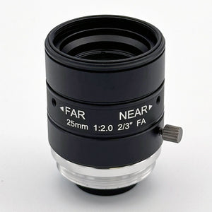
focal length = (working distance × sensor width) / field width Example: 300mm working distance, 8.8mm sensor width (2/3"), 120mm field width → (300 × 8.8) / 120 = 22mm. At this fixed 300mm working distance, round down to ≤22mm and crop to hit 120mm exactly; using the 25mm CIL544 instead requires extending working distance to (120 × 25) / 8.8 = 341mm to keep the full field.

Top lenses for medical imaging and device inspection by use case

Match the lens to the job first, then the sensor. Miniature instrument optics start with the M8/M7 series, compact embedded modules run on M12, and bench instruments or inspection stations that need an adjustable iris move to C-mount. The table maps Commonlands stock lenses to the use case each one fits, using the specs published on each product page. All ship same-day on orders placed before 12 PM PST.

Use case Lens Mount EFL Why this pick
Miniature instrument optics (endoscope tip, catheter modules) M8 / M7 series M8 / M7 Short, fixed Smallest diameter when the package dominates every other constraint. Fixed aperture and limited image circle. Tip geometry varies too much for one stock SKU, so start from the collection.
Compact embedded module (diagnostic camera) CIL085 M12 8.2mm 1/1.7" coverage, 57° FOV, -0.9% distortion, 8.9mm image circle. Mid-FOV workhorse for an embedded module.
Diagnostic instrument optics (longer working distance) CIL121 M12 21.8mm Finite-conjugate M12 corrected for a 500mm working distance, so corners hold at instrument range where a long-conjugate lens softens.
Instrument / cart-based imaging (compact C-mount) CIL561 C-mount 6mm 1/1.7", 76° FOV, -2% distortion, adjustable F/2.4 iris for depth-of-field control on a bench head.
Instrument / cart-based imaging (high resolution) CIL544 C-mount 25mm 1.1" 20MP-class coverage, 17.6mm image circle, 130mm to infinity WD for larger-sensor imaging heads.
Device inspection / UDI reading CIL052 M12 5.2mm -0.1% distortion holds Data Matrix and barcode geometry across the field, up to 1/1.8" at F/3.4.
Sterile-line inspection (sealed) CIL059 M12 5.9mm IP67-sealed variant for liquid or vapor exposure, F/1.7 to F/5.6 selectable at procurement. About -4% distortion suits contrast-based checks, not geometry-critical reads.
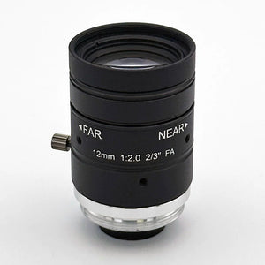
Packaging / PCB inspection (depth of field) CIL522 C-mount 12mm F/1.4 to F/16 adjustable iris, 0.4% distortion, 11.4mm image circle. Stop down for depth of field over package height variation.
How we picked

Each row starts from the inspection or imaging task, not the catalog. Distortion drives the geometry-sensitive tasks (UDI reading, assembly verification), an adjustable iris covers the depth-of-field cases (packaging, PCB), image circle sets the sensor ceiling, and sealing gates the wet or sterile lines. Every spec shown is published on the linked product page; confirm field of view for your sensor with the field of view calculator before ordering.

Off-the-shelf vs. custom

These stock lenses fit prototyping, bench diagnostics, and inline inspection stations, where the optic sits behind a window or housing and never touches the patient. Patient-contact optics, lenses that have to survive repeated sterilization cycles (autoclave, EtO, gamma), and any lens that must carry regulatory qualification inside a finished device need a custom development path, not a catalog part. If that is your case, send the requirement to engineering for a custom quote.
7mm M12 Lens GMSL Camera

CIL068-F2.5-M12A650

Low Distortion 6.8mm M12 Lens

$49.00

View details

What should a team validate before locking a lens into production?

Validate image quality across the full sensor at the actual working distance, CRA compatibility with the specific sensor, focus stability across the operating temperature range, contamination resistance where the device contacts clinical surfaces, mechanical reliability under the field environment, and manufacturability of the lens-to-sensor alignment. Use the real sensor and illumination source for every check, not a substitute.

Image quality testing

  • Measure resolution (MTF) at center, mid-field, and corner at the actual working distance, using the actual sensor.
  • Measure distortion across the full sensor diagonal and confirm it falls within the software pipeline's tolerance.
  • Evaluate flat-field shading uniformity to detect CRA-induced vignetting in the corners, with the real sensor and illumination source.
  • Verify color accuracy under the intended illumination, and confirm any IR-cut or wavelength filter is in place and effective.
  • Confirm focus is achievable at the required working distance and that depth of field covers the expected variation range. Use the depth of field calculator as a starting estimate, then verify physically.

Environmental and reliability testing

  • Test focus stability across the expected operating temperature range; thermal expansion of the lens barrel and mount shifts the focus plane.
  • Validate mechanical durability under the vibration and shock profile the device will see in field use.
  • Confirm humidity resistance and any ingress requirements are met by the lens assembly design, not assumed from a datasheet.

Contamination handling and manufacturability

  • If the device contacts clinical surfaces, define the cleaning protocol and verify lens coatings and sealing are compatible with the approved cleaning agents.
  • Confirm the lens front element is accessible for cleaning if required, or that device sealing keeps contamination out of the optical path.
  • Define the lens-to-sensor alignment tolerance and confirm the assembly process (manual focus, active alignment, or potting) achieves it repeatably at production volume.
Procurement note

MOD and working distance are not published on every lens datasheet; confirm directly with the manufacturer before locking a design around an assumed value. Commonlands publishes distortion specs for the lenses referenced above, and MTF test data is available for select lenses; confirm per-SKU test coverage with engineering.

A board-level M12 camera inspecting rows of clear medical vials and tubing
Even lighting and sharp optics catch fill and seal defects.

Frequently asked questions

What is a medical imaging lens?

A medical imaging lens is an optical assembly selected to produce repeatable, geometrically accurate images for clinical, diagnostic, or device-integrated applications. It is chosen for sensor compatibility (image circle, CRA), distortion performance for the software pipeline, wavelength response for the illumination source, mount class for the device package, and reliability in the operating environment. Options span miniature M8 lenses for endoscope-style modules through larger C-mount lenses for bench instruments.

How do I choose a lens for a medical device camera?

Define six parameters before evaluating any lens: required field of view and working distance, sensor format and pixel pitch, the package constraint that sets mount class, the distortion tolerance the software pipeline requires, the CRA budget the sensor imposes, and the wavelength stack the illumination uses. Sensor and lens should be selected together; choosing a lens first and fitting the sensor afterward tends to produce re-spins.

Should I use M8, M12, or C-mount for medical imaging?

Use M8 or M7 when the device package forces extreme miniaturization, such as capsule endoscopes or catheter-tip modules. Use M12 for compact embedded modules; most models cover sensors up to about 1/1.8 inch, with select models reaching 1/1.7 inch to 1/1.6 inch. Use C-mount when the sensor is larger, the system needs an adjustable iris for depth-of-field control, or the instrument housing has room for the larger lens body.

Do medical imaging lenses need low distortion?

It depends on the software pipeline. Image registration, spatial measurement, and segmentation all assume a rectilinear mapping from scene to sensor, so distortion is a direct source of error there. For pipelines that only classify or detect, moderate distortion is often acceptable. For measurement-critical pipelines, target distortion below 2%, and below 1% where possible.

Why does chief ray angle matter in medical imaging?

Chief ray angle (CRA) is the angle at which the principal ray enters the sensor at a given image height. Small-pixel CMOS sensors use microlenses tuned to an expected CRA; a lens CRA that exceeds the sensor's tolerance at the edge causes corner shading and color non-uniformity that flat-field calibration alone cannot fully correct. Both the lens CRA profile and the sensor's datasheet CRA spec must be known and matched. See the chief ray angle and mismatch guide.

How does sensor size change lens choice in medical imaging?

Sensor size sets the required image circle, the mount classes that can cover it, and the focal length needed for a given field of view. A larger sensor needs a larger image circle and a longer focal length at the same working distance, which tends to push designs from M12 toward C-mount. Always check the lens image circle against the sensor's actual active-area diagonal from the datasheet, not the nominal format number. See the CMOS sensor size guide.

When are IR-cut or other optical filters needed in medical imaging?

IR-cut filters are needed whenever the sensor responds beyond visible light and enough near-infrared energy reaches the scene to bias color. Halogen, incandescent, and ambient daylight carry significant NIR; dedicated NIR LEDs do by design, but standard white LEDs emit little energy beyond 700nm. The IR-cut question is driven by the sensor's NIR response plus whatever NIR actually reaches the scene. NIR-pass or narrow-band filters are needed instead when the application specifically images in the near-infrared or fluorescence-adjacent bands. Browse optical filters for compatible options.

What machine vision lens should I use for medical device inspection?

Start with the inspection task, not the lens catalog. Assembly verification and UDI reading benefit from low distortion. Packaging and seal inspection create depth-of-field pressure from package height variation, favoring an adjustable-iris C-mount lens. PCB inspection inside electronic medical devices shares both requirements. Dimensional metrology is the one case where telecentric optics may be justified; most other tasks do not need them. Commonlands options include the CIL052 (5.2mm M12, -0.1% distortion), CIL059 (5.9mm M12, IP67 variant), CIL522 (12mm C-mount, adjustable iris), and CIL544 (25mm C-mount, 20MP+ coverage).

Does UDI reading on medical devices need a low-distortion lens?

Yes, for most UDI reading applications. A lens with significant barrel or pincushion distortion compresses or stretches Data Matrix and barcode symbol elements near the image periphery, degrading decode confidence on marks that are already small or low contrast. Distortion below 0.3% TV (TV distortion, a picture-height edge metric that yields a smaller number than the corner-referenced optical/rectilinear distortion percentage; the exact ratio depends on sensor aspect ratio) keeps symbol geometry close enough to nominal for reliable decoding across the full field. The CIL052 5.2mm M12 lens has -0.1% rectilinear distortion, which is well inside that target even accounting for the TV/rectilinear difference, and covers sensors up to 1/1.8 inch.

Is a telecentric lens required for medical device inspection?

No, not for most tasks. Telecentric lenses hold apparent object size constant across working distance, which matters for dimensional metrology on parts with real height variation. Assembly verification, UDI reading, packaging inspection, and PCB checks are pass/fail tasks that do not need magnification constancy. A low-distortion C-mount lens covers them at lower cost, and it offers the adjustable iris that telecentric lenses typically lack. Commonlands does not currently sell telecentric lenses.

What should a team validate before locking a lens into production?

Validate image quality across the full sensor at the actual working distance (resolution, distortion, shading, color accuracy), CRA compatibility with the specific sensor, focus stability across the operating temperature range, contamination resistance if the device contacts clinical surfaces, mechanical reliability under the field environment, and manufacturability of the lens-to-sensor alignment. Use the real sensor and illumination source for every check, not substitutes.

How do I calculate the focal length for a medical imaging or inspection station?

Focal length = (working distance × sensor width) / field-of-view width. This is the exact rectilinear relationship, not an approximation. At 300mm working distance, an 8.8mm sensor width, and a 120mm field width, the required focal length is (300 × 8.8) / 120 = 22mm. At that fixed 300mm working distance, round down to a focal length at or below 22mm and crop to the target field, since a longer lens narrows the field below 120mm. To use a 25mm lens instead, extend the working distance to (120 × 25) / 8.8 = 341mm. Verify with the field of view calculator and the EFL calculator.

Can one lens cover every inspection task on a medical device line?

Usually not without tradeoffs. UDI reading needs low distortion, packaging inspection needs depth-of-field range, and PCB checking needs both plus resolution. A low-distortion C-mount lens with adjustable iris covers the widest range of tasks and lets a line standardize on fewer SKUs, even when individual stations run different aperture and working-distance settings. Verify each station independently with the FOV calculator and DOF calculator.

Have a sensor and working distance in hand?

Commonlands manufactures M12 and C-mount lenses for medical imaging cameras and medical device inspection stations, with published distortion specs and MTF test data available for select lenses. ISO 9001:2015 certified. Samples ship same-day on orders placed before 12 PM PST.