

How to Choose Focal Length for Machine Vision: Formula, Sensor Size, and Selection Steps
Focal length is a geometry problem with a specific answer for each setup. This guide covers the formula, what effective focal length actually means, the full selection sequence, and when a telephoto is the right call.

To choose a focal length for machine vision, start from three measured numbers: the scene width the camera must cover, the working distance from the front of the lens to the target, and the active width of your sensor. The required focal length is EFL = (WD × sensor_width) / FOV_width for rectilinear lenses, a far-conjugate approximation that holds closely at normal machine vision working distances, where the distance is long compared with the focal length.
Pick the nearest stock focal length, then verify distortion, depth of field, and image circle before ordering. The field of view calculator checks any lens and sensor pairing in seconds.
How do I calculate the focal length I need?
Required focal length equals active sensor width multiplied by working distance, divided by required scene width. A 1/2.7" sensor (5.37mm active width) imaging a 120mm-wide part from 400mm needs (5.37 × 400) / 120 = 17.9mm, which makes 16mm and 21.8mm the practical high-resolution stock candidates.
This geometry is a far-conjugate approximation, exact only in a pinhole ray model. Real finite-conjugate imaging follows Gaussian conjugates measured from the principal planes, and the error grows with magnification. Covering a 100mm scene from 300mm with a 14.1mm-wide sensor (m ≈ 0.14), the formula gives 42.3mm, while the thin-lens form (Hecht, Optics, 5th ed., §5.2) f = WD × m / (1 + m) gives about 37mm. Fisheye and F-theta lenses use different projections. Use datasheet FOV values for those.

What is effective focal length?
Effective focal length (EFL) is the distance from a lens's rear principal plane to its focal point when the lens is focused at infinity. With the sensor size and the object and image conjugates, it sets field of view and magnification. The mm value printed on a lens listing (6mm, 12mm, 35mm) is the EFL. Nominal EFL does not change with working distance: a 12mm lens stays a 12mm lens at 500mm or 100mm. The effective value drifts slightly with focus breathing in internal-focus designs.
| Term | What it is | What it controls |
|---|---|---|
| EFL (effective focal length) | Optical parameter of the lens prescription | Field of view and magnification, with sensor and conjugates |
| BFL / MBFL (back focal length) | Per-lens rear spacing dimension | Holder and adapter clearance (whether the lens can reach focus) |
| FFD (flange focal distance) | Mount standard specification | Lens interchangeability (17.526mm C-mount, 12.526mm CS-mount, none for M12) |
The EFL calculator runs the rectilinear math for common sensor formats and flags where the wide-angle caution applies.
How do you select a machine vision lens, step by step?
- Define the field of view. Write the scene dimensions in millimeters at the target plane, plus a 10–20% margin for placement tolerance. A 200mm-wide board becomes a 240mm design field.
- Measure the working distance. Working distance runs from the front of the lens to the target. Early in a project it is a design variable. Once the mechanical design commits, it hardens into a number you measure rather than choose. For M12 builds, the nearest reachable distance follows from the lens prescription, holder height and thread engagement, sensor-stack clearance, and the corner sharpness the task demands. Ask Commonlands engineering to confirm it. C-mount working distance varies by product, typically 100mm to infinity. The working distance guide covers this hardening.
- Pull the active sensor dimensions. Pixel count × pixel pitch from the sensor datasheet, never the nominal format label. The image sensor database lists active areas for common parts.
- Set the smallest feature to resolve. Divide scene width by horizontal pixel count for ground sampling distance (mm/pixel). Sensor Nyquist is a sampling ceiling, 1000/(2 × pixel_pitch_um) lp/mm, or two samples per line pair. Two pixels across the smallest feature is a separate inspection rule of thumb, and the headroom you need above it depends on contrast, the algorithm, and your inspection or decoder vendor's minimum sampling spec. The spatial resolution guide covers the math.
- Calculate the focal length. EFL = (WD × sensor_width) / FOV_width, then shortlist the nearest stock values. The EFL calculator does this in one step.
- Choose the mount family. M12 fits compact, light, board-level builds. C-mount fits larger sensors and an adjustable iris. Its focus ring's internal mechanism and near-limit behavior vary by design, so verify both on the datasheet. CS-mount uses the same thread as C-mount with a shorter 12.526mm flange focal distance, compared with 17.526mm for C-mount. The lens mount guide compares thread, flange, and coverage in detail.
- Verify image quality. Run four checks: image circle at least as large as the sensor diagonal, distortion against the application's position-error budget, depth of field spanning the object height range (run the depth of field calculator), and lens MTF at the feature's spatial frequency (see the MTF curve guide).
Should you choose a short, medium, or long focal length?
Commonlands M12 lenses span all three focal length bands, and a medium range near 5mm to 16mm fits most factory inspection setups. Treat the bands as rough groupings, not hard thresholds. Shorter lenses tend to buy scene coverage and depth of field from close range. Longer lenses tend to buy pixel density at the cost of shallower depth of field. Distortion follows the lens projection and correction, not focal length alone. Start medium unless the geometry forces you elsewhere. The depth of field guide covers the long-lens trade.
| Focal length range | Field of view (relative) | Distortion (design-dependent) | Depth of field | Pixel density on target | Typical use |
|---|---|---|---|---|---|
| Short (<5mm) | Wide | Design- and field-dependent | Deep | Lower | Wide coverage, navigation, autonomous mobile robots (AMRs) |
| Medium (5–16mm) | Moderate | Varies | Moderate | Moderate | General inspection, barcode reading |
| Long (>16mm) | Narrow | Design- and field-dependent | Shallow | Higher | Fine feature detection, metrology |
The field of view column is relative, with no degree ranges, because the angle depends on the sensor as much as the lens: the same 12mm lens reads 25.2° on a 1/2.7" sensor and 33.3° on a 1/1.8" sensor. Compute the actual angle for your lens with the angle of view calculator before classifying a candidate as wide or narrow.
Which M12 focal lengths cover most applications?
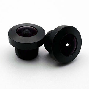
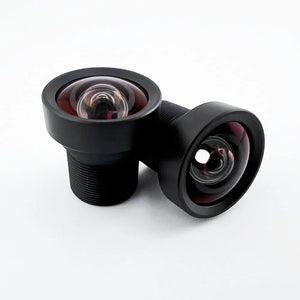
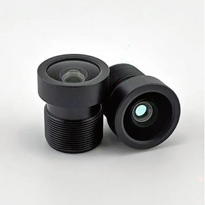
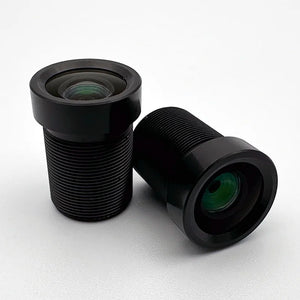
Three stock M12 lenses span the working range for most machine vision setups: 3.3mm for wide coverage, 6.2mm as the general-purpose default, and 12.5mm where pixel density matters. The full M12 catalog runs 0.8mm fisheye to 100mm telephoto.
Commonlands stocks M12 lenses in the US, with aperture and filter variants listed on each product page. Orders placed before 12 PM PT ship the same day from San Diego, CA.
Commonlands M12 lens options by focal length. Field-of-view angles are diagonal (DFOV) at each lens's stated reference circle, which can be smaller than its full image circle.
| Lens | EFL | Sensor format | FOV (diagonal) | Distortion | Price | Best for |
|---|---|---|---|---|---|---|
| CIL036 | 3.3mm | See product page | 89° at the 6.4mm reference circle | -0.7% TV | $19 | Wide field with low distortion in tight installations |
| CIL062 | 6.2mm | Up to 1/1.8" | 60° at 7.2mm reference circle (9.0mm full circle) | -2% rectilinear at 8.8mm | $19 | Balanced general inspection and the default starting point |
| CIL125 | 12.5mm | See product page | 35° at 7.9mm reference circle | -1.4% optical | $39 | Tighter field with higher pixel density for fine features and labels |
TV distortion is measured as the image-height deviation at the frame edge, rectilinear (optical) distortion against the paraxial ideal ray height, and F-theta distortion against the r = f·θ reference. Because the references differ, the percentages are not directly comparable row to row.
When should you choose a telephoto machine vision lens?
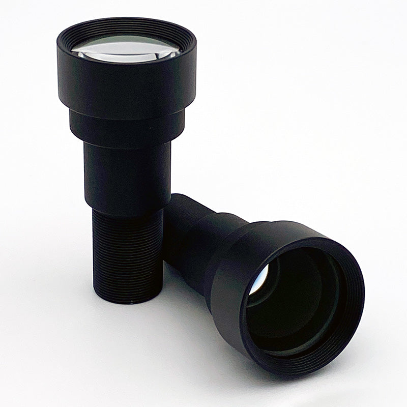
Choose a telephoto machine vision lens when the target is small or distant and the camera cannot move closer. As a rough guide, that means the target fills only a small fraction of the frame with the lens you have. Commonlands telephoto M12 options run 12.5mm to 50mm, with 75mm and 100mm models at the long end of the catalog. All of them trade scene coverage for magnification, tighter focus tolerance, and higher vibration sensitivity.
In machine vision, "telephoto" is used loosely for any long-EFL lens. Strictly it names a construction shorter than its focal length, so a long-focus lens is not necessarily telephoto (Smith, Modern Optical Engineering, 4th ed.). Doubling the EFL halves the linear field of view at the same working distance and doubles the apparent target size. Typical applications are aerial inspection from drones, traffic monitoring at distance, overhead conveyor lines, and barcode or OCR reading at long standoff.
Long lenses are less forgiving than short ones. Depth of field shrinks rapidly as focal length grows, so a focus setting easy at 6mm becomes critical at 35mm, and image shift from platform wobble scales with focal length. Plan stiffer mounts, lock focus, and re-verify after mechanical service. The focusing guide covers the procedure.
Telephoto is also often the wrong answer: to monitor a wide area or run on a vibration-heavy platform, a shorter focal length tolerates the pointing error and motion that would push a narrow frame off target.
Near-focus behavior differs by mount. A C-mount telephoto focuses by ring rotation. The ring may drive the whole cell, a front group, or a cam, and near-stop sharpness is design-specific, so confirm minimum object distance with Commonlands engineering. M12 telephotos are rigid barrels focused by thread rotation: thread engagement, the barrel shoulder, and rear-element clearance set hard near-focus limits, so short standoffs demand deep holders, and close-range sharpness falls to conjugate-dependent aberrations such as field curvature, not center focus alone.
Selected telephoto M12 lenses reach 1/1.7" sensor coverage in a fixed-aperture board-lens package, the right fit for drones, embedded systems, and weight-limited payloads. Move to C-mount when the sensor is larger, when you need an iris to stop down for depth of field, or when lighting is too dim to fix at a fixed aperture. The low-light section of the f-number guide covers that trade.
Commonlands telephoto M12 lenses from 12.5mm to 50mm, ordered by focal length.
| Part | EFL | Format | Resolution | Aperture | Price |
|---|---|---|---|---|---|
| CIL125 | 12.5mm | Up to 1/2" | 12MP | Fixed | $39 |
| CIL121 | 21.8mm | Up to 1/1.7" | 12MP+ | Fixed | $70 |
| CIL350 | 35mm | 1/1.7" | 8–10MP | Fixed | $59 |
| CIL051 | 50mm | Up to 1/1.8" | 12MP | Fixed | $79 |
The resolution column names the sensor class each design targets. MP ratings are unstandardized labels with no aperture, field, spectrum, or contrast conditions attached. Confirm against the measured MTF data and pixel-pitch pairing on each product page.
What if the calculated focal length does not exist?
Round to the nearest stock focal length and recompute the field of view. Rounding shorter gives extra coverage you can crop, the safe default when installation geometry is not locked. Rounding longer gives less coverage and is only acceptable once you confirm the scene still fits the sensor, the call when the feature is small and resolution outweighs coverage. If neither works, a 10–20% working distance change is a starting point we use, provided magnification, clearance, perspective, and lighting allow.
Commonlands stocks M12 focal lengths in discrete steps (2.6mm, 3.3mm, 3.6mm, 6.2mm, 8mm, 12.5mm, 14.2mm, 16mm, 18mm, 19mm, 21.8mm, 25mm, and up), so a calculated value will often land between them. The steps cluster tightly from 12mm to 25mm, where the nearest option usually sits within about 10% of the calculated value. Some intermediate steps, including the 18mm and 19mm options, are lower-resolution designs rated for 2MP sensors and below, so check the resolution rating before shortlisting.
Whatever the rounding decision, validate with physical test images before locking the design: mount the lens at the planned distance, image a calibration target or the real part, and confirm the features resolve and the scene fits. Test images catch corner vignetting, focus error at the target plane, and distortion in the actual part geometry that the math does not.

Frequently asked questions
The Commonlands FOV calculator runs these formulas for any sensor. The answers below explain the math behind it.
How do I calculate focal length from field of view and working distance?
Multiply the active sensor width by the working distance and divide by the required scene width: EFL = (WD × sensor_width) / FOV_width. A 1/2.7" sensor (5.37mm active width) at a 400mm working distance covering a 120mm scene needs (5.37 × 400) / 120 = 17.9mm, so 16mm and 21.8mm are the high-resolution stock candidates (18mm and 19mm options exist as lower-resolution designs for 2MP sensors and below). The EFL calculator runs this directly.
What is effective focal length?
Effective focal length (EFL) is the distance from a lens's rear principal plane to its focal point when the lens is focused at infinity. With the sensor size and the object and image conjugates, it sets field of view and magnification. The mm value on a machine vision lens listing (6mm, 12mm, 35mm) is the EFL, not the back focal length and not the flange focal distance.
What steps go into machine vision lens selection?
Machine vision lens selection runs in a fixed order: define the required field of view, measure the working distance, and pull active sensor dimensions from the sensor datasheet. Then set the smallest feature to resolve, calculate focal length with EFL = (WD × sensor_width) / FOV_width, and choose the mount family. The final step is to verify image circle, distortion, depth of field, and MTF.
What are telephoto machine vision lenses?
Telephoto machine vision lenses are long focal length designs that produce a narrow field of view and higher magnification at a given working distance. Common telephoto M12 options run 12.5mm to 50mm and image small or distant targets (aerial inspection, traffic monitoring, long-standoff barcode reading) at the cost of tighter focus and vibration tolerances.
What happens if my ideal focal length does not exist?
Choose the nearest stock focal length and recompute the field of view. Rounding shorter adds coverage you can crop in software, which is the safer direction. Rounding longer cuts coverage and requires confirming the scene still fits the sensor. A 10–20% working distance change is a starting point we use when magnification, clearance, perspective, and lighting allow. Verify any candidate with the field of view calculator before ordering.
Get a focal length recommendation
Send your working distance, scene size, and sensor part number to the Commonlands engineering team in San Diego and they will run the numbers with you. Orders placed before 12 PM PT ship the same day.