

Barcode Reading in Machine Vision: A Lens Guide for OCR, Document Scanning, and Biometrics
Pixel coverage, depth of field, and distortion control set the optical margin decoding software depends on, across codes, characters, pages, and faces.

Optics is one cause of read failure among several. Print or mark quality, illumination geometry, specular glare, motion, exposure, damaged quiet zones, symbol conformance, and the decoder itself each fail independently.
This guide covers the optical share: pixels, focus, and clean geometry on the feature that matters, which differs by task. Fix the sampling requirement first, using the decoder vendor's spec and your own read-rate testing. Then check depth of field, distortion, and illumination at the real working distance.
What data-capture reading needs from the optics
Pixel coverage of the smallest feature
The decoder needs a minimum number of pixels across the narrowest element: the X dimension (narrowest bar or space) for 1D barcodes, the module for 2D Data Matrix and QR codes, character body height for OCR, iris diameter for biometrics. Under-sampling it is a common cause of read failure.
Contrast transfer at the feature's spatial frequency
Even with enough pixels, poor MTF at the feature's spatial frequency softens edges, so a megapixel rating alone does not qualify a lens. Check MTF at the sensor plane against your read-rate requirement.
Depth of field across the working-distance range
Conveyor sag, stacked labels, curved packaging, and stand-off variation create a working-distance range the lens must hold focus across. A circle of confusion of about 1 pixel at the sensor is a geometric proxy, not a measured limit: usable depth of field depends on the lens's through-focus MTF. Use the depth of field calculator to estimate it and the depth of field guide for the derivation.
Controlled distortion across the usable field
Distortion deforms bars, modules, characters, and geometry near the frame edges, where barrel (negative) or pincushion (positive) displacement is largest. Most decoders tolerate it near the center. A low-distortion lens cuts that risk.
Illumination and exposure matched to the task
At line speed, long exposure smears features across pixels: a 250mm/s conveyor during a 2ms exposure creates 0.5mm of blur, enough to erase a 0.3mm bar. For biometric and document capture the constraint shifts to illumination uniformity and, for iris, a specific NIR wavelength.

How 1D barcodes, 2D Data Matrix and QR codes, and direct-part-mark codes differ
Code types differ in what they demand from the optics and illumination.
1D barcodes (Code 128, GS1-128, Code 39, ITF-14)
One-dimensional barcodes encode data along a single axis, so sampling is driven along the reading axis and blur along the bars costs less than blur across them. That margin narrows when code rotation varies, bar height is short, quiet zones are damaged, or an image-based decoder searches the whole frame. The driving parameter is the X dimension, the narrowest bar width, which runs from 0.25mm on small labels to 1mm or more on pallet codes.
2D Data Matrix and QR codes
Two-dimensional codes store data in both axes, so every module must resolve in both directions. That raises the bar on MTF uniformity across the full field, makes edge distortion a real failure mode, and requires uniform focus across the whole code. QR alignment markers tolerate perspective and rotation a little better than Data Matrix.
Direct-part-mark (DPM) codes
DPM codes are laser-etched, dot-peened, or chemically etched into metal, so contrast comes from surface texture rather than ink and runs much lower than on a printed label. MTF at the module frequency has to stay high without an aperture so small that diffraction eats the contrast, and the illumination (angled, dark-field, or coaxial with a polarizer) has to make shallow features visible.
A comparison of common failure modes
| Failure symptom | Likely optical cause | First parameter to check | Likely fix |
|---|---|---|---|
| Decode fails only near image edges | Distortion or off-axis aberrations | Distortion spec and edge MTF at the field coverage in use | Use a lower-distortion lens; keep the code within the usable image circle |
| Decode fails at line speed but passes static | Motion blur from long exposure | Exposure time vs conveyor velocity in mm/s | Reduce exposure time; add brighter or strobed illumination |
| Decode fails across a range of distances | Depth of field too shallow | Aperture vs a 1-pixel CoC proxy; usable depth follows through-focus MTF | Stop down within the diffraction limit; increase illumination to compensate |
| Intermittent failures on small codes or characters | Pixel coverage below minimum threshold | Pixels across the narrowest bar, module, or character height | Reduce field of view, use a longer focal length, or move the camera closer |
| Decode fails only on shiny labels or metal DPM | Specular glare washing out contrast | Illumination angle and specular reflection geometry | Move the source out of the specular path: diffuse, dark-field, or coaxial geometry, or cross-polarized source and lens. A bandpass filter rejects ambient light, not glare at the source wavelength |
How to choose the focal length and working distance for barcode reading
This holds in the pinhole rectilinear ray model with WD referenced to the entrance pupil; real finite-conjugate imaging needs principal-plane conjugates, and a housing-referenced WD adds an unstated offset (Hecht, Optics, 5th ed., §5.2). For distortion-corrected values at wide fields, use the field of view calculator.
A worked example: label reading on a packaging line
A 1/2.3" sensor (6.17mm × 4.55mm active area) reading a 60mm-wide label at 400mm needs an EFL near 400 × 6.17 / 60 = 41.1mm. At a 400mm conjugate, the finite-conjugate estimate adds sensor width to the denominator: 400 × 6.17 / 66.17 is roughly 37mm, and housing-measured WD shifts it further, so bracket 37-41mm against the FOV calculator before choosing the catalog EFL.
With 4000 pixels across the 6.17mm width, each pixel covers 60 / 4000 = 0.015mm in the scene, so a 0.25mm X-dimension bar spans 0.25 / 0.015 = 16.7 pixels. Common industry floors run about 2 to 3 pixels per X dimension for 1D decode and 4 to 8 pixels per module for 2D symbols. Compare those against your decoder vendor's minimum sampling spec.
ISO/IEC 15415 and 15416 are print-quality grading standards: they fix measurement conditions, synthetic aperture, and analysis rules, not a universal pixels-per-module count. Take the verification sampling requirement from the setup those standards specify and from the verifier's manual.
For barcode standoffs, an M12 assembly's near limit is set by the prescription, holder thread engagement, sensor-stack clearance, and the sharpness the decoder needs, so have Commonlands engineering confirm it before freezing the read distance. C-mount lenses typically run 100mm to infinity, varying by model. MOD is measured from the front of the lens and not always published, so verify it for close-range electronics reading. See the minimum detectable size guide for pixel coverage and FOV at close range.
Lens selection for OCR and character reading
Pixel density and the 20-pixel heuristic
A common starting point is around 20 pixels across the body height of the smallest character: x-height for lowercase, cap height for the all-caps alphanumerics common on industrial labels. The ratio between the two belongs to the typeface, so measure the glyphs on your actual label rather than halving the nominal size. Accuracy tends to fall off below about 10 pixels, though the real minimum shifts with font, stroke width, contrast, preprocessing, and the OCR engine.
To check a design, multiply the sensor pixel count on the relevant axis by that body height as a fraction of the scene dimension. A 1920-pixel axis over an 80mm scene with a 4mm character body gives 1920 × (4/80) = 96 pixels, well clear; at 0.8mm it drops to 19, which is marginal. When under-sampling is the cause, the fix is a longer focal length or a higher-resolution sensor, not a different engine.
Focal length and mount
Longer focal lengths earn their place when the camera cannot move closer and a shorter lens would render characters too small: license plates, overhead text, serial numbers at a fixed robot stand-off. Choose focal length and stand-off together. Moving a shorter lens closer to preserve framing keeps magnification approximately constant; at the same f-number and blur criterion it does not generally increase object-space depth of field. Evaluate vibration sensitivity and clearance for the actual mounting geometry.
M12 fits most compact OCR, and a low-distortion M12 such as the CIL052 gives -0.1% rectilinear distortion with the system built around its fixed F#. C-mount wins when depth-of-field control matters, when the sensor exceeds the M12 image circle (typically above 1/1.8 inch), or when it needs a longer focal length.
Lens selection for document scanning
Document scanning is a flat, static imaging problem. The lens must cover the full page at the working distance, put enough pixels on the smallest detail, and keep straight edges straight. A low-distortion fixed-focal lens is the right default. Telecentric optics are not needed here and are not a current Commonlands product.
Distortion and rolling shutter
Barrel or pincushion distortion is worst at the corners, exactly where a document's edges sit. Downstream requirements set the tolerance: dimensional accuracy, OCR bounding-box registration, or multi-page alignment call for lower distortion. The CIL052 holds -0.1% rectilinear distortion for embedded page geometry. Rolling shutter is usually fine on a static scene, though steady light avoids banding from pulsed sources.
Lenses for face and iris biometric capture
Iris imaging: NIR illumination on a small feature
The human iris is roughly 11-12mm across, and standards-oriented capture commonly targets 100 to 200 pixels across that diameter, because recognition depends on fine radial and furrow detail. Hitting that usually means a longer focal length or a shorter working distance than face capture.
Iris also depends on illumination near 850nm: it reveals texture that visible light captures inconsistently and is far less sensitive to ambient lighting and eye color. That needs the standard NIR stack, no IR-cut filter in the path, a bandpass filter matched to the illuminator, and a lens that transmits 850nm. See 850nm vs 940nm and NIR imaging in machine vision for the full stack.
Face recognition: even illumination and low distortion
Face recognition covers a larger feature, so pixel-coverage pressure is lower, but even illumination and low distortion dominate. A single off-axis source throws shadows that shift with subject position, and barrel or pincushion warps facial geometry near the edges where off-center subjects sit. Many systems add 850nm NIR so capture stays consistent day and night, which again needs the NIR stack above.
Commonlands does not publish or validate biometric matching-accuracy figures; those depend on the algorithm, enrollment quality, and population statistics, not the lens. Verify accuracy claims with the biometric software vendor.
Commonlands lens examples for data-capture applications
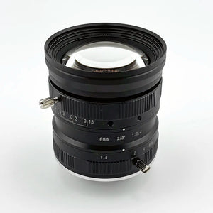
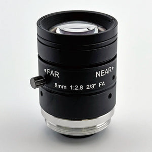
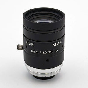
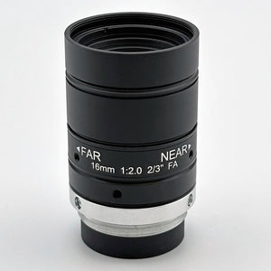
Top lenses for barcode reading, OCR, and document scanning
| Task | Recommended lens | Mount and EFL | Why it fits | Link |
|---|---|---|---|---|
| 1D and 2D label reading on a line | CIL064 large format | M12, 6mm | The 86° field suits wide or multi-lane belts where several labels cross at once; one small dense code samples better with a longer EFL. The 11mm image circle covers sensors up to 2/3", including 1/1.6" parts such as the IMX676, so pixel density at that field comes from sensor resolution. F/2.9 fixed; the product table rates it for 10MP at 2µm pitch. Confirm MTF at the required field positions and working distance. | View CIL064 |
| Close-range DPM and small codes | CIL052 low distortion | M12, 5.2mm | Pixel density follows magnification, not focal length alone: at a fixed sensor and working distance a shorter EFL widens the field and lowers it. This 5.2mm design earns the slot by framing a small code from a short standoff, and -0.1% rectilinear distortion keeps modules decodable near the frame edge. F/3.4 fixed, up to 1/1.8" sensors. | View CIL052 |
| OCR and document scanning | CIL532 C-mount | C-mount, 12mm | +0.05% distortion across an 11.1mm image circle suits full-page geometry, and the F/2.0-F/16 adjustable iris trades aperture for depth of field on curved labels or uneven documents. Up to 2/3" sensors at 12MP. | View CIL532 |

Frequently asked questions
What lens should I use for OCR in machine vision?
Start with a fixed focal length lens sized to put at least 20 pixels across the smallest character's body height, x-height for lowercase and cap height for all-caps. A low-distortion M12 lens such as the CIL052 suits moderate working distances for embedded OCR and label reading. When the camera must stay back, a longer focal length preserves character size on the sensor. C-mount is preferred when an adjustable iris is needed for depth-of-field control, or when the sensor exceeds the M12 lens's image circle, typically above 1/1.8 inch.
What lens should I use for document scanning in machine vision?
Start with document size, working distance, and sensor size, then calculate the focal length so the full page fills the sensor field at that working distance. Choose a low-distortion fixed focal lens matched to those numbers rather than the widest lens that technically fits. For embedded setups, a low-distortion M12 lens such as the CIL052 is practical. For bench or archival scanning, where aperture control and larger sensors matter, a C-mount lens gives more control.
What lens is needed for iris recognition?
Iris recognition needs an NIR-transmitting lens paired with roughly 850nm illumination and a matching bandpass filter, sized to put enough pixels across the iris diameter (commonly cited targets run from about 100 to 200 pixels across the iris for standards-grade capture). The lens and filter stack must pass 850nm efficiently. A standard visible-only IR-cut path blocks the wavelength the sensor needs. See the Commonlands NIR imaging guide for the full filter and illumination stack.
What is different about reading 1D barcodes versus Data Matrix codes?
1D barcodes encode data in bars along one axis and can be decoded from a single scan line, so blur along the bars costs less than blur across them. That margin shrinks when orientation varies, bars are short, or quiet zones are damaged. The driving parameter is the X dimension, the narrowest bar width. Data Matrix and QR codes encode data in both axes, so every module must resolve in two directions, raising the requirements on MTF uniformity, distortion, and focus across the code.
What is needed for face recognition camera optics?
Face recognition needs even illumination across the capture volume, low distortion so facial geometry is not warped near the frame edges, and enough pixels across the interpupillary distance or face width for the matching algorithm in use. Many access-control and identity systems add NIR illumination around 850nm so capture is consistent regardless of ambient visible lighting, which requires a lens and filter path that transmits that wavelength.
Need help matching a lens to a data-capture application?
Describe the code type, character size, document geometry, or biometric modality, with working distance, sensor, and line speed. Commonlands engineering can work through pixel coverage, depth of field, and illumination before you commit to hardware.