



How to match a lens to your embedded sensor
A lens-sensor mismatch shows up as vignetting, color shading, or wasted resolution. Four parameters need to line up: image circle versus sensor diagonal, CRA versus sensor microlens design, lens MTF versus sensor Nyquist frequency, and back focal length versus your sensor stack.
Image circle must cover the sensor diagonal
The lens projects a circular image; your rectangular sensor sits inside that circle. An image circle smaller than the sensor diagonal produces vignetting at the corners. Moderate oversizing is usually acceptable for coverage; run the same CRA, clearance, stack, and MTF checks as any pairing. Undersizing vignettes the corners and fails whenever the image must fill the full frame. Circular-image fisheyes that place the whole image circle inside the frame are the deliberate exception.
| Sensor format | Diagonal |
|---|---|
| 1/4" | 4.5mm |
| 1/3" | 6.0mm |
| 1/2.5" | 7.2mm |
| 1/2.3" (IMX477 class) | 7.9mm |
| 1/1.7" | 9.5mm |
A lens rated for 1/2.5" sensors covers any sensor that size or smaller; it will vignette on a 1/1.7" sensor. Datasheets list image circle in millimeters or as a sensor format designation, and the two are not always published with matching precision, so verify against your sensor's actual diagonal rather than assuming format labels align exactly between vendors. See sensor size and lens compatibility for the full coverage math.
Resolution: the lens MTF must clear the sensor's Nyquist frequency
A 12MP sensor with 1.55µm pixels has a monochrome Nyquist frequency near 322 lp/mm, and a Bayer sensor samples each color channel more coarsely than that. If the lens cannot resolve the frequency your task needs at your working aperture, the sensor's extra resolution goes to waste. Check the lens MTF chart at the aperture you intend to shoot.
Commonlands uses 20%-30% MTF at Nyquist as a starting point for embedded work, not a standard: what you actually need follows the contrast and SNR of the task, how much aliasing the pipeline tolerates, and which field positions carry the measurement. Validate it against your own images. The MTF curve guide explains how to read these charts.
Work the focal length math directly
Run your sensor size, target field of view, and working distance through the field of view calculator or the EFL calculator to get the required focal length for your system, consistent with the same formula used above.
How chief ray angle affects embedded camera image quality
Chief ray angle (CRA) is the angle at which the lens delivers light to a given point on the sensor. Small-pixel sensors, common at 1.4µm-2.5µm in embedded cameras, use microlenses over each pixel tuned to a specific CRA curve. That curve runs from roughly 0 to 15 degrees at the edge on industrial and machine vision sensors, up to 25 to 35 degrees on mobile-class parts, so pull the curve for your sensor rather than assuming a typical value. When the lens CRA does not track the sensor's design CRA, you get color shading (red, green, and blue channels fall off differently toward the edges) and reduced corner brightness that software cannot fully correct, because the mismatch is wavelength- and angle-dependent at the pixel level rather than a uniform gain error.
This matters most on the small-pixel sensors that dominate embedded and board-camera designs. Sensor datasheets specify a CRA curve; lens datasheets specify a matching CRA spec or curve. When selecting a lens for a sensor with sub-2µm pixels, check that the two curves track across the field, not just at the center. Curve overlap is a screen, not an acceptance test: the tolerable difference depends on the full ray cone at each field point, so on working F-number, plus the wavelength band, the pixel and filter stack, and the corner shading and MTF loss your pipeline accepts. Settle it with flat-field and corner MTF measurements. The full mismatch mechanics and matching procedure are in the chief ray angle and mismatch guide.
CRA mismatch is easy to miss during bring-up because center-field image quality looks fine. The problem shows up at the corners and edges, often only under specific lighting or after a sensor revision changes the microlens design. Verify CRA compatibility before committing to a lens for a new camera module, not after color shading appears in the field.
Board-level integration on Jetson and Raspberry Pi camera modules

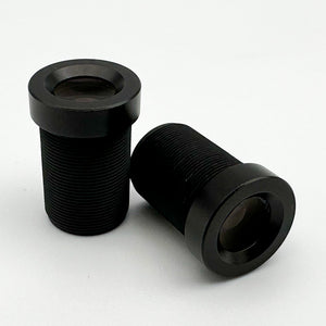
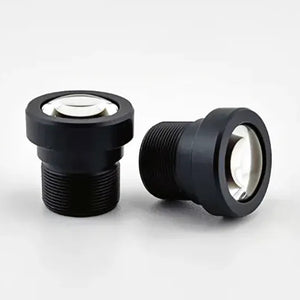
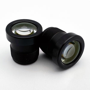
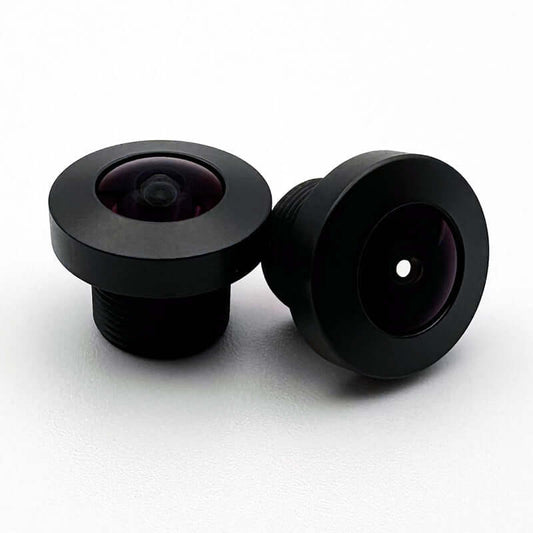
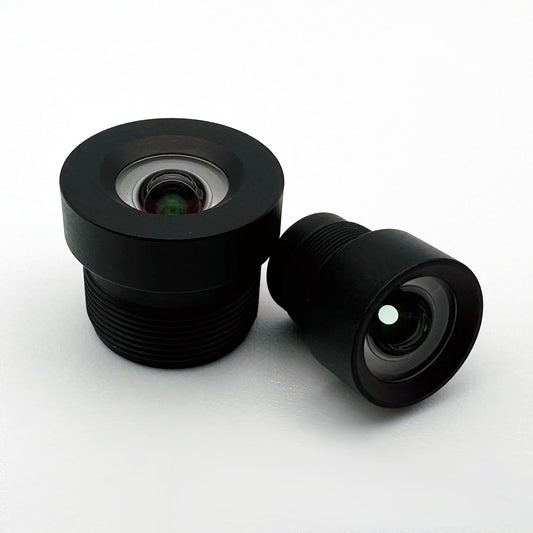
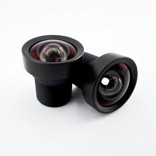
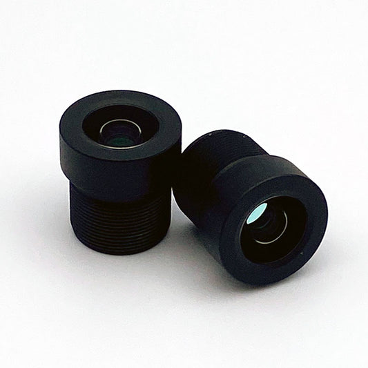
MIPI CSI-2 is an electrical interface between the sensor and the host processor, not a lens mount, and no compute platform defines one. Mount style belongs to the camera board. Plenty of Jetson and Raspberry Pi camera boards do carry an M12 holder soldered or clipped to the PCB, which is why M12 dominates this space, but Raspberry Pi's own line covers three cases: fixed integrated optics on Camera Module 2 and Camera Module 3, and the High Quality Camera, sold both in a C/CS-mount version that ships with a C-mount adapter and in a native M12-mount version.
Common sensors on these boards are the IMX477 (High Quality Camera), IMX219 (Camera Module 2), and IMX708 (Camera Module 3). Read the mechanical drawing for the board you are building on before ordering a lens. Because M12 has no standardized flange distance, focus is set entirely by how far the lens threads into the holder, and back focal length (BFL) varies by lens design.
That variability helps at the board level. When the same lens design moves onto a module whose cover glass and IR filter stack is a different thickness, a holder of the correct height brings the sensor back to the lens's focus position, which is cheaper than requalifying a lens. Confirm holder height against the lens's specified back focal length and your full sensor stack (bare sensor, cover glass, IR filter, any spacer) before finalizing the PCB footprint. The M12 lens holder selection guide covers holder height selection and thread engagement in detail.
Holder height only buys back focus. A thicker or thinner plane-parallel stack sitting in a converging beam adds its own spherical aberration and axial color, and any wedge in that stack tilts the image plane. Moving the lens along the axis corrects none of that.
A different filter also moves the passband, shifting where an IR-corrected design lands in focus, and an interference cut filter shifts its cut-off with ray angle, so the corner response moves differently from the center. Measure corner MTF and color shading on the new module rather than assuming the refocus closed the gap.
Multi-camera Jetson and Raspberry Pi designs raise the integration bar further. A stereo pair should be closely matched in focal length and distortion profile, because those set the disparity-to-range scale and the rectification accuracy, and the rig needs synchronized exposure plus extrinsics that hold their calibration. Back focal length is the one difference that does not need matching: each module is focused individually, which absorbs it.
Bulk-buying from a single production lot reduces optical unit-to-unit spread but does not eliminate it, so verify focus at the corners of the field on each unit during bring-up, not only at the center.
The power, size, and cost triangle
Embedded lens selection is a three-way tradeoff: optical performance, physical footprint, and unit cost, with power draw as a secondary axis tied to footprint. Unlike a fixed industrial inspection station, embedded systems usually cannot spend freely on any one corner of that triangle without giving up ground on the other two.
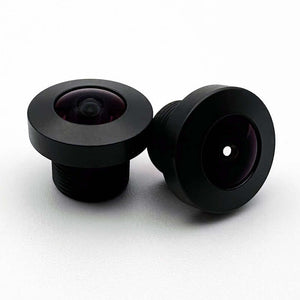
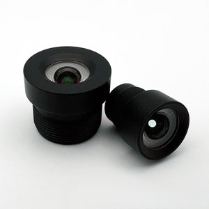
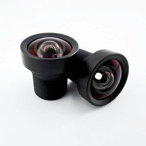
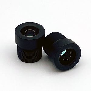
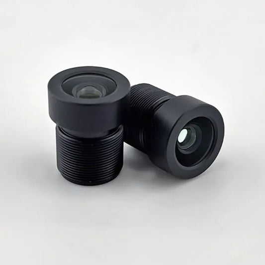
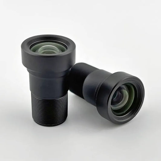
M12 lenses sit at the small-footprint, low-cost corner. A 3g-15g lens with a fixed aperture draws no power itself and costs a fraction of an industrial optic, but gives up the adjustable iris and ring-driven focus that C-mount designs such as Commonlands' provide. C-mount and CS-mount sit at the opposite corner: an iris ring lets you trade depth of field for light throughput on demand and a focus ring refocuses without re-threading the lens, but the lens weighs 3x-10x more and costs more per unit. For a drone or handheld device on battery power, that weight difference is a meaningful chunk of flight time or user fatigue, not just a spec sheet number.
Aperture control also interacts with power in a less obvious way. C-mount's adjustable iris is only practical in machine vision because illumination is usually programmatically controlled (structured lighting, LED ring lights, backlight arrays), which lets the system stop down for depth of field without starving the sensor of light. Embedded systems that rely on ambient or uncontrolled lighting cannot always make that trade, which pushes the decision back toward a fixed-aperture M12 lens paired with a fast F-number instead.
Most embedded designs default to M12 with a fixed aperture and accept the loss of iris control, reserving C-mount for the subset of embedded applications, such as high-resolution inspection modules or outdoor enclosures that call for a specific ruggedized SKU, where the extra size and cost buy something the application actually needs. Ruggedization itself is a selective, SKU-specific feature rather than a property of the C-mount format as a whole.
Key specs to evaluate before you commit
Focal length
Shorter focal length means wider field of view for a given sensor. 2mm-4mm gives ultra-wide coverage for obstacle avoidance. 4mm-8mm covers general-purpose vision. 8mm-16mm gives narrow field of view for inspection and barcode reading. Use the EFL calculator to solve for focal length from your target coverage area and working distance; see how to choose focal length for the full method.
F-number (aperture)
A lower F-number admits more light: an F/1.4 lens passes roughly four times the light of an F/2.8 lens. The tradeoff is a shallower depth of field. Prioritize F/1.4-F/1.8 for low-light embedded vision; F/2.0-F/2.8 is reasonable where depth of field matters more than light gathering. Run the numbers in the depth of field calculator, and see F-number in machine vision for the underlying relationship.
Distortion
Barrel distortion bends straight lines into curves. No fixed percentage is required by an application: what a measurement pipeline tolerates depends on the camera model it calibrates to, how well features localize at the field positions being measured, the accuracy the task needs, and whether the compute budget covers an undistort pass. Distortion the calibrated model captures gets corrected; distortion the model does not fit becomes residual error. Standard wide-angle M12 lenses commonly run 10%-20% distortion, and Commonlands low-distortion models bring that under 1%, which keeps an uncalibrated pinhole model usable. See the low-distortion lens guide.
Thermal stability
Thermal range is wider outside a climate-controlled factory. An embedded camera in a vehicle or an outdoor enclosure can see -30 degrees C to +70 degrees C across a day, and a drone camera can move from sun-heated ground to cold altitude in minutes. Thermal expansion and the temperature dependence of refractive index shift the focal plane as the assembly heats and cools, and at fast apertures on small-pixel sensors the depth of focus is tight enough that a poorly athermalized lens can drift out of focus with no mechanical fault involved. Construction is one screening input, not a thermal spec: suitability is settled by a focus or MTF measurement across your operating temperature range on the assembled lens, holder, and sensor, and Commonlands can run that test on request.
Weight
Matters most for drones, handheld devices, and robotic arms, where added mass affects flight time, user fatigue, or servo load. M12 lenses typically run 3g-15g; C-mount lenses typically run 50g-200g. Choose the lightest lens that still clears your optical requirements.
IP rating
IP67, defined in IEC 60529, means dust-tight plus 30 minutes under a meter of water. That is an immersion test, not a rain or spray test. IP6K9K (industry shorthand IP69K) comes from ISO 20653, a road-vehicle standard with its own high-pressure, high-temperature jet procedure. They are separate standards run as separate tests, so cite them separately rather than as one washdown rating.
Ratings apply to the tested lens variant in its mounted configuration under the standard's water and dust exposures; they do not cover steam, detergents, repeated sanitation cycles, or the rest of the camera. Where the lens sits behind a sealed window in a rated housing, the housing carries the requirement and the lens may need no individual code. Match the test to the exposure the camera actually sees.
See the IP rating guide for test methods, and note that ruggedization is a selective feature on specific SKUs, not a property of all C-mount or M12 lenses; see the ruggedized lens guide.
Camera-module vendors such as Arducam and e-con Systems ship boards with optics already paired to the sensor, which is convenient when you want a single fixed bill of materials. A discrete, spec-controlled M12 lens is the better engineering choice when you need to match chief ray angle to a specific sensor, add or swap an IR-cut or bandpass filter, or hold a distortion and image-circle spec across a production run. Run your sensor, target field of view, and working distance through the field of view calculator or EFL calculator before locking focal length.